Fast reactor having reflector control system and neutron reflector thereof

a control system and reactor technology, applied in nuclear engineering problems, nuclear elements, greenhouse gas reduction, etc., can solve the problems of excessive increase in reactivity around the middle burn-up stage, gradual decrease of reactivity and becoming considerably low, and increase in reactivity tend to be saturated, so as to reduce reactivity and increase reactivity. , the effect of decreasing reactivity

Inactive Publication Date: 2008-11-06
KK TOSHIBA
View PDF12 Cites 9 Cited by
  • Summary
  • Abstract
  • Description
  • Claims
  • Application Information

AI Technical Summary

Benefits of technology

[0035]In order to solve the problems of related techniques described above, the present invention was made, and an object of the present invention is to provide a fast reactor having a reflector control system and a neutron reflector therefor, the fast reactor being capable of maintaining the reactivity of reactor core at a constant rate so as to obtain an efficient plant having a constant thermal power. The fast reactor having a reflector control system, described above, can be achieved by, without performing control of a lifting speed of a reflector and control of a flow rate of water, decreasing the change in reactivity of the fast reactor with time, and in particular, by suppressing a decrease in reactivity at a last burn-up stage and an increase in reactivity at a middle burn-up stage.
[0044]Furthermore, it has also been known that when ferritic stainless steel is used instead of austenitic stainless steel, the swelling is suppressed; hence, although the reflector reactivity is inferior to that of austenitic stainless steel as described above, resistance against swelling is superior, and hence ferritic stainless steel has been used as a reflector material. However, when austenitic stainless steel which contains chromium and nickel at a high ratio is partially used, the axial direction dependency of reflector reactivity can be advantageously changed.
[0047]In the fast reactor having a reflector control system, according to the present invention, the change in reactivity with time can be decreased which occurs when the lifting speed of the reflector is maintained constant. In particular, when the reactivity is maintained as constant as possible by suppressing the decrease in reactivity at the last burn-up stage and the increase in reactivity at the middle burn-up stage, a plant having a constant thermal power and a high operational efficiency can be operated while control of the flow rate of water is not carried out or while the control thereof is only performed within a small control range.
[0048]In addition, since the control of the lifting speed of the reflector becomes unnecessary, reactivity input caused by malfunction of a control device can be eliminated in principle, and hence the safety can be improved. Even when the control of the lifting speed is performed, since the control range thereof can be reduced, the reactivity input caused by malfunction of a control device can be reduced, and hence the safety can also be improved.
[0049]Similar effect can be obtained if differential reflector reactivity per unit movement upward can be maintained constant by changing axially the fissile material concentration in the reactor core. Then, the change in total reactivity due to fuel burn-up and reflector movement can be suppressed during the entire serviceable life thereof. Hence, a plant can be obtained having a uniform thermal output and a high operation efficiency.

Problems solved by technology

However, after the middle burn-up stage, the reactivity is gradually decreased and becomes considerably low at the last burn-up stage.
In order to increase the reactivity at the last stage, when the reflection ability of the reflector is increased (for example, the thickness thereof is increased), the reactivity is excessively increased around the middle burn-up stage.
However, when the degree of insertion exceeds 60% (insertion depth of 120 cm), the increase in reactivity tends to be saturated.
By the reasons described above, as long as the lifting speed of the reflector is maintained constant, the decrease in reactivity caused by the burn-up of core fuel cannot be totally compensated for by the movement of the reflector in the axial direction.
Since the decrease in reactivity causes the decrease in thermal power, the thermal power with time cannot be maintained constant, and a small amount of thermal power can only be obtained around the last burn-up stage; hence, as a result, an uneconomic plant is disadvantageously to be constructed.
However, the control of the lifting speed may cause accidents in some cases due to excessive increase in reactivity resulting from malfunctions or failures of control devices.

Method used


Image

  • Fast reactor having reflector control system and neutron reflector thereof
  • Fast reactor having reflector control system and neutron reflector thereof
  • Fast reactor having reflector control system and neutron reflector thereof

Examples


first embodiment

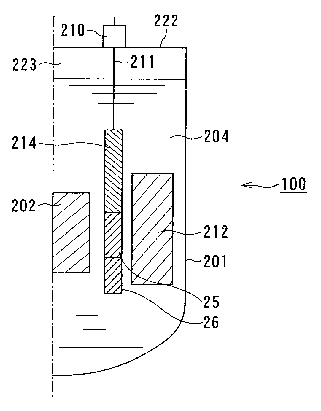
[0098]FIG. 1 is a vertical cross-sectional view of a fast reactor 100 of a first embodiment according to the present invention. In this embodiment, the same reference numerals of the constituent elements of the fast reactor 200 shown in FIG. 33 designate constituent elements substantially equivalent thereto, and descriptions thereof will be omitted.

[0099]The fast reactor 100 is different from the related fast reactor 200 in terms of the structure of the neutron reflector 209. That is, although the neutron reflector 209 of the fast reactor 200 is a one-piece product which is not divided and which is formed of the same material in the axial direction, the neutron reflector of the fast reactor 100 is formed of an upper reflector 25 and a lower reflector 26.

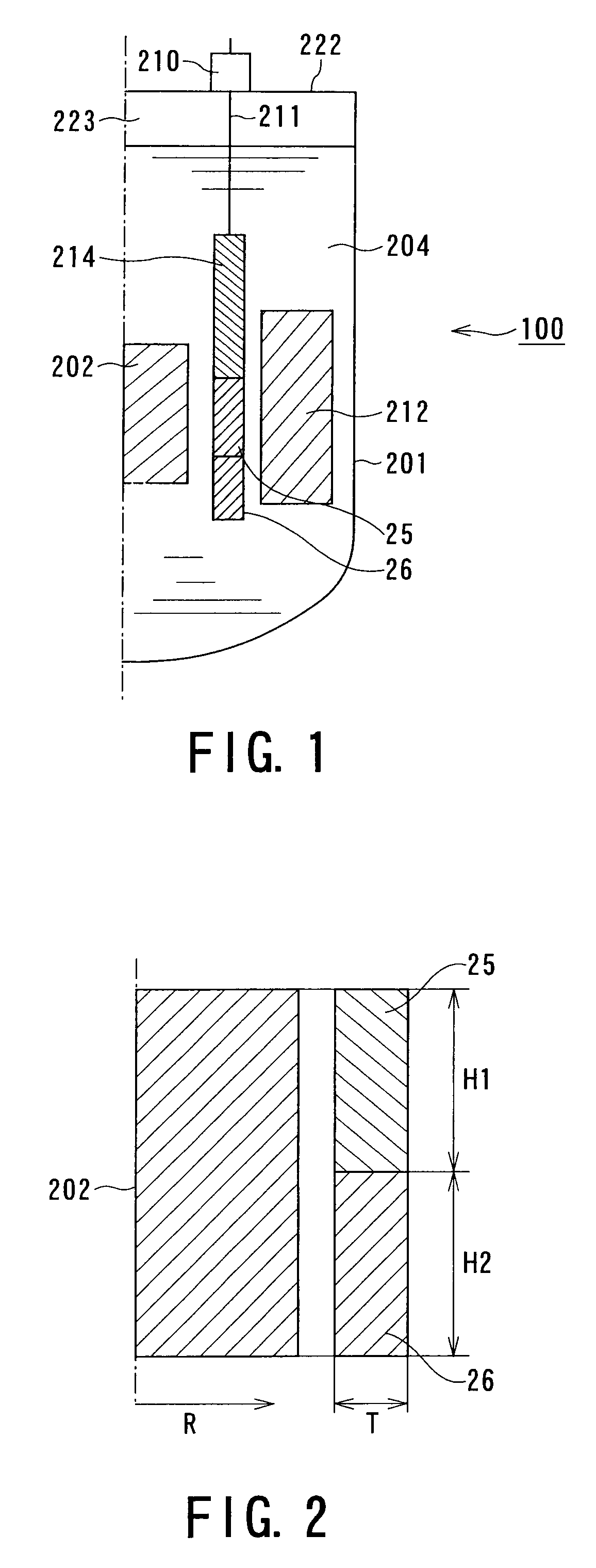
[0100]FIG. 2 is an enlarged vertical cross-sectional view showing the positional relationship among the reactor core 202, the upper reflector 25, and the lower reflector 26 of the fast reactor 100.

[0101]As shown in FIG. 2, for exampl...

second embodiment

[0109]FIG. 6 is a vertical cross-sectional view of a fast reactor having a reflector control system of a second embodiment according to the present invention, and in particular, is an enlarged view showing the reactor core 202 and reflectors 25, 26, and 27. In this figure, constituent elements corresponding to those shown in FIG. 1, which is a vertical cross-sectional view of the fast reactor of the first embodiment, are omitted. However, the elements are identical to those shown in FIG. 1 except for the reflector portion shown in FIG. 6. Heights H3, H4, and H5 of the upper reflector 25, the center reflector 27, and the lower reflector 26, respectively, are such that H3 is 70 cm, H4 is 60 cm, and H5 is 70 cm.

[0110]In addition, the upper reflector 25 is made of austenitic stainless steel, the center reflector 27 is made of ferritic stainless steel, and the lower reflector 26 is made of graphite. As for the degree of reactivity, as shown in FIG. 43, graphite is high, ferritic stainles...

third embodiment

[0112]FIGS. 8A, 8B, and 8C are vertical cross-sectional views each showing a reflector of a fast reactor having a reflector control system of a third embodiment according to the present invention. The reflector is formed of a single composition of ferritic stainless steel. However, in the lower region of the reflector, in FIG. 8A, the thickness thereof is gradually increased toward the bottom side, and the reflector in FIG. 8B has a large and uniform thickness. As shown in FIG. 46, since the reflection ability is increased as the thickness is increased, the similar effect as that of the first embodiment can be obtained. The reflector shown in FIG. 8C has a larger thickness at the upper portion than that at the central portion, and the lower portion has the largest thickness; hence, the similar effect as that of the second embodiment can be obtained.

[0113]The dimensions of the individual reflectors are described below. In the example shown in FIG. 8A, an upper thickness T1 is set to ...


PUM


Abstract

A fast reactor having a reflector control system is provided which decreases the change in reactivity of the reactor core with time without performing control of a reflector lifting speed and that of a water flow rate. The above fast reactor has a liquid metal coolant, a reactor core immersed therein, and a neutron reflector which is provided outside the reactor core and which is moved in a vertical direction for adjusting leakage of neutrons therefrom for controlling the reactivity of the reactor core. The neutron reflector described above is gradually moved in an upward direction with the change in reactivity caused by fuel burn-up, and at least a part of a lower region of the neutron reflector is a high reflection region having a high neutron reflection ability as compared to that of the other region. The high reflection region is located from the bottom to a place between one fourth and one half of the height of the neutron reflector from the bottom end thereof.

Description

CROSS-REFERENCE TO RELATED APPLICATIONS[0001]This application is a divisional of U.S. application Ser. No. 11 / 060,625, filed on Feb. 18, 2005, the contents of which are incorporated herein by reference, and is based on and claims the benefit of priority from the prior Japanese Patent Application Nos. 2004-042822, filed on Feb. 19, 2004; 2004-087422, filed on Mar. 24, 2004; and 2004-157319, filed on May 27, 2004.BACKGROUND OF THE INVENTION[0002]1. Field of the Invention[0003]The present invention relates to fast reactors having a reflector control system and neutron reflectors therefor, and more particularly, relates to a fast reactor having a reflector control system and a neutron reflector therefor, the fast reactor controlling reactivity of a reactor core through adjustment of leakage of neutrons leaked therefrom by moving the neutron reflector in a vertical direction which is disposed outside the reactor core immersed in a liquid metal coolant.[0004]2. Description of the Related ...

Claims


Application Information

Patent Timeline
Patent Type & Authority Applications(United States)
IPC IPC(8): G21C7/32G21C7/06
CPCG21C7/28G21C11/06G21Y2002/301G21Y2002/304G21Y2004/30G21Y2004/403Y02E30/34Y02E30/35Y02E30/39Y02E30/30
Inventor YOKOYAMA, TSUGIOYAMAOKA, MITSUAKIMORIKI, YASUYUKIKATO, RYOMATSUBOI, YASUSHIMATSUDA, ATSUKO
Owner KK TOSHIBA
Why Eureka
Try Eureka