Minimally invasive surgical driver

a driver and minimally invasive technology, applied in the field of surgical instruments, can solve the problems of less than desirable bone opening, and achieve the effect of convenient maintenance and easy disassembly for cleaning

Inactive Publication Date: 2008-11-06
SYMMETRY MEDICAL MFG INC
View PDF25 Cites 13 Cited by
  • Summary
  • Abstract
  • Description
  • Claims
  • Application Information

AI Technical Summary

Benefits of technology

[0010]An advantage of the present invention is that the open frame allows for easy maintenance and cleaning of the driver.
[0011]Another advantage of the present invention is that it is easily disassembled for cleaning.
[0012]Yet another advantage of the present invention is that the removable input shaft readily mates with the drive shaft that is pinned to other link members.
[0013]Still another advantage of the present invention is that the axis of the output shaft is offset from the input axis of the driver.

Problems solved by technology

Flexible shafts allow the reamer to travel along a path in a non-linear manner resulting in a less than desirable opening in the bone.

Method used


Image

  • Minimally invasive surgical driver
  • Minimally invasive surgical driver
  • Minimally invasive surgical driver

Examples


Embodiment Construction

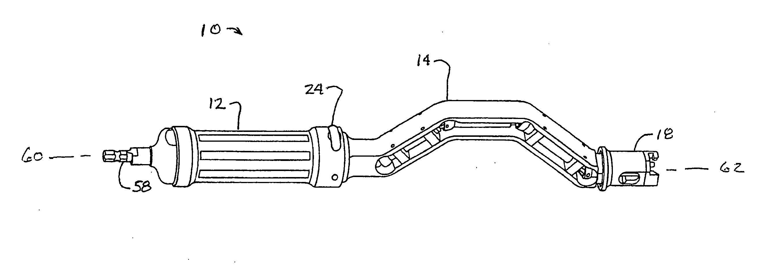
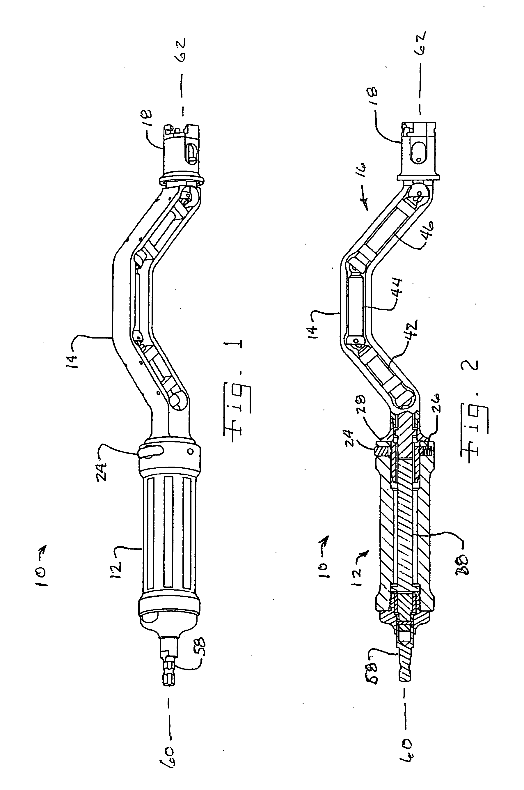
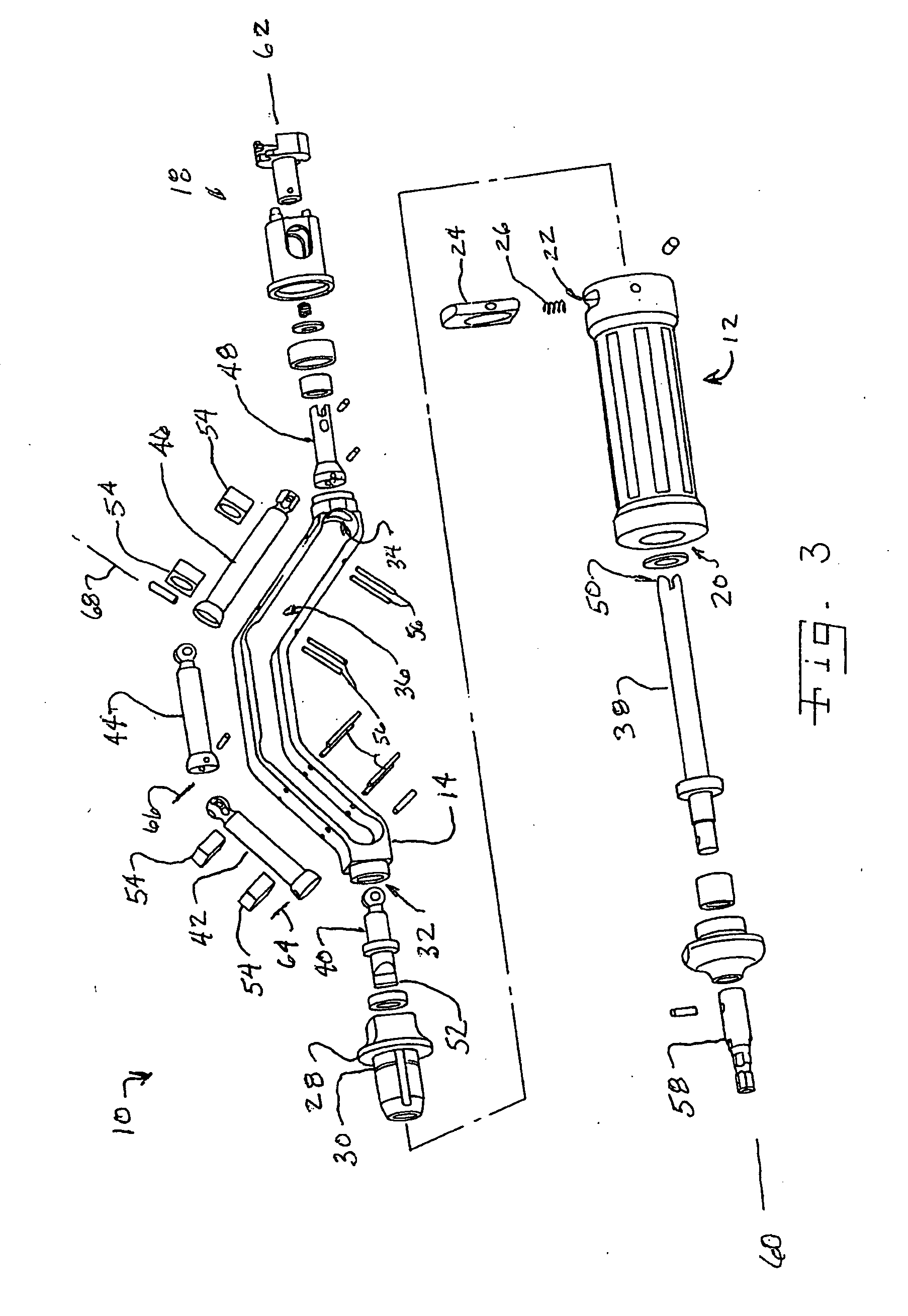
[0019]Referring now to the drawings, and, more particularly to FIGS. 1-3, there is shown an embodiment of a surgical driver assembly 10, which includes a handle assembly 12, a drive body 14, a drive train assembly 16 and a drive head 18. Handle assembly 12 includes an axial opening 20 and a radial opening 22 in which a pushbutton 24 and biasing device 26 is associated. A transition collar 28 interfaces with a portion of frame 14 and an end of handle 12 to secure frame 14 to handle 12. Transition collar 28 includes a groove 30, which interfaces with pushbutton 24 such that handle assembly 12 is connected to the rest of driver assembly 10 until pushbutton 24 is depressed against biasing device 26, thereby moving a feature in pushbutton 24 away from groove 30 allowing handle 12 to be removed from transition collar 28. This allows for quick disassembly of driver assembly 10 so that individual items may be maintained and / or cleaned.

[0020]Drive body 14, also known as an open frame 14 incl...


PUM


Abstract

A method of removing bone material including the steps of drivingly connecting a bone removal tool to an output shaft; and rotating a plurality of drive shafts in an open frame, one of the plurality of drive shafts being connected to the output shaft.

Description

CROSS REFERENCE TO RELATED APPLICATIONS[0001]This is a division of U.S. patent application Ser. No. 11 / 238,354, entitled “MINIMALLY INVASIVE SURGICAL DRIVER”, filed Sep. 29, 2005, which is incorporated herein by reference.BACKGROUND OF THE INVENTION[0002]1. Field of the Invention[0003]The present invention pertains generally to surgical instruments and, more particularly, to surgical instruments such as surgical tool drivers suited for use in orthopeadic surgical procedures.[0004]2. Description of the Related Art[0005]An orthopeadic driver assembly can be used to ream or cut a bone and thereby form the bone into a predetermined shape for receiving an orthopeadic implant. For example, an orthopeadic reamer assembly may be used to shape the interior or exterior surface of a bone. A rotary tool provides the rotational force and is connected to the driver, which is connected to the reamer. The driver generally has a shaft end and a drive end. The reamer may have a typically hemispherica...

Claims


Application Information

Patent Timeline
Patent Type & Authority Applications(United States)
IPC IPC(8): A61B17/00A61B19/00
CPCA61B2017/0046B25G1/04B25G3/28A61B17/1631A61B17/1633A61B17/1666A61B17/1617A61B17/1684
Inventor MYERS, REESE K.BERTHUSEN, ANDREW H.MENDENHALL, BRYAN
Owner SYMMETRY MEDICAL MFG INC
Why Eureka
Try Eureka