Tack anchor systems, bone anchor systems, and methods of use

a technology of bone anchors and anchor systems, applied in the field of bone anchor systems and anchor systems, can solve the problems of adding contamination risk, reducing working space, and tedious procedures, and achieve the effects of enhancing tissue placement, preventing suture slippage, and enhancing tissue placemen

Active Publication Date: 2008-11-06
HOWMEDICA OSTEONICS CORP
View PDF99 Cites 404 Cited by
  • Summary
  • Abstract
  • Description
  • Claims
  • Application Information

AI Technical Summary

Benefits of technology

[0018]In some embodiments, a suture loop is coupled to a tissue and two ends of the suture are coupled to a two bar locking assembly. The suture ends pass though the opening of a first locking ring and then pass under and wrap around an upper bar of a second locking ring. The suture passes though a gap between the locking elements, under the upper bar of the first locking ring, and then around the upper bar of the first locking ring. Proximal ends of the suture are accessible. Optimization of tissue placement relative to a bone anchor may be achieved by individually tensioning each of the suture ends. Once in place, the suture is compressed between the locking elements, preventing the suture from slipping or moving in an undesirable direction. In some embodiments, the locking elements reversibly engage after the tissue has been placed.
[0019]In some embodiments, apparatuses and methods for securing tissue to bone allow direct tactile feedback of the tension in the suture between the tissue and the bone is obtained. In some embodiments, apparatuses and methods for securing tissue to bone allow tensioning both ends of a suture individually to enhance placement of the tissue with respect to the bone. In some embodiments, apparatuses and methods for securing tissue to bone allow a suture to be locked in place without tying a knot.
[0020]In some embodiments, an apparatus is provided that includes a bone anchor member. The bone anchor member may be securely disposed in a hole drilled in a bone. A suture length may be coupled between the bone anchor member and tissue. In some embodiments, a suture length is coupled between a plug portion that fits within a bore of the bone anchor member and the tissue. One or more ends of the suture may be individually tensioned to enhance the placement of the tissue with respect to the bone and secure the suture.
[0021]In some embodiments, a system is provided to insert a bone anchor to a site in a bone that allows for a bone anchor to be placed into a site in a bone and thread a suture therethrough.
[0022]In some embodiments, a self-contained suture passer is provided to allow a surgeon to form and retrieve a suture loop in a tissue. The suture passer may be operated without the need of a separate mechanical means to retrieve the suture.

Problems solved by technology

This procedure is often tedious and time-consuming.
Most devices require the use of a separate tool to grab onto and retrieve the suture, thereby further reducing the working space and adding risk of contamination, or leading to a tendency for the suture to deform or collapse suture is manually retrieved.
In addition, tying the knot in this manner is particularly difficult during endoscopic surgeries, where the visual field for the surgeon is severely limited by the narrow surgical area.

Method used


Image

  • Tack anchor systems, bone anchor systems, and methods of use
  • Tack anchor systems, bone anchor systems, and methods of use
  • Tack anchor systems, bone anchor systems, and methods of use

Examples


Embodiment Construction

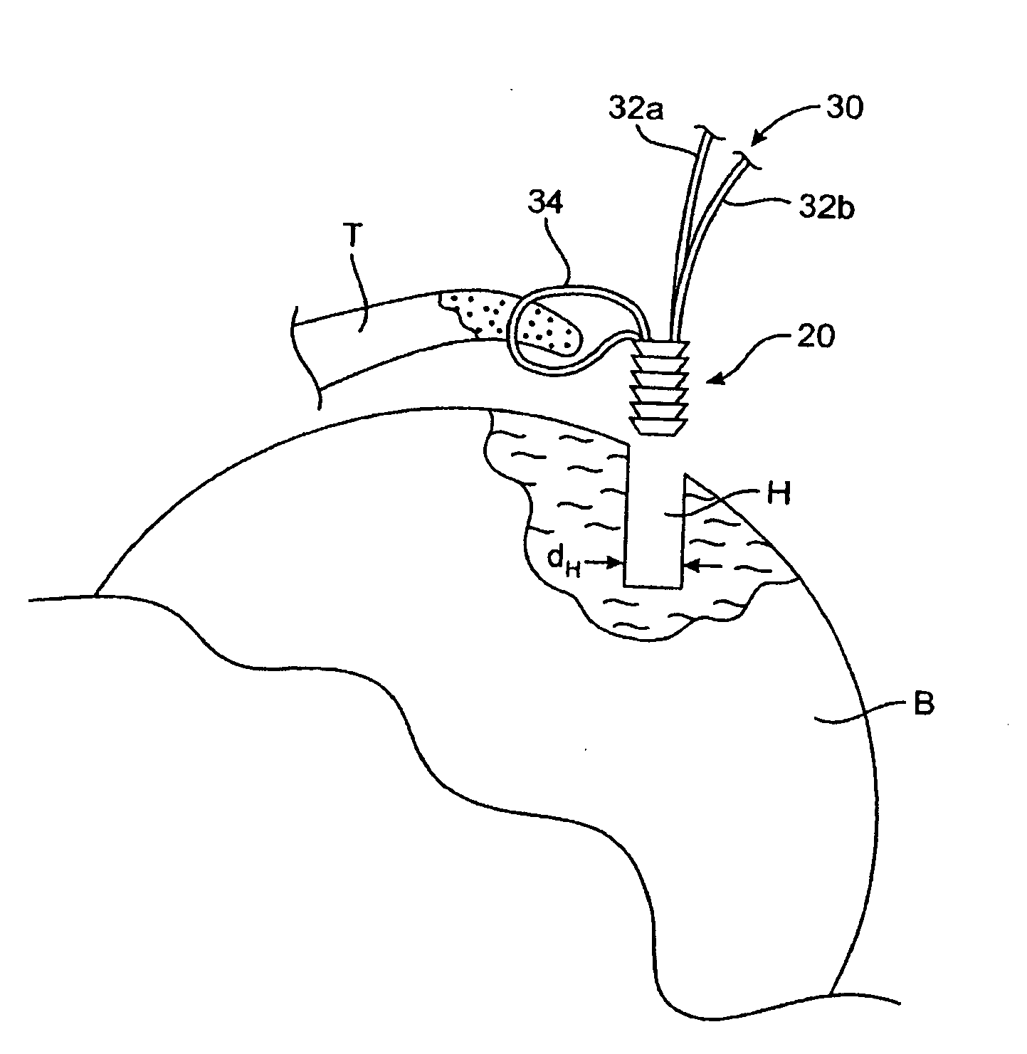
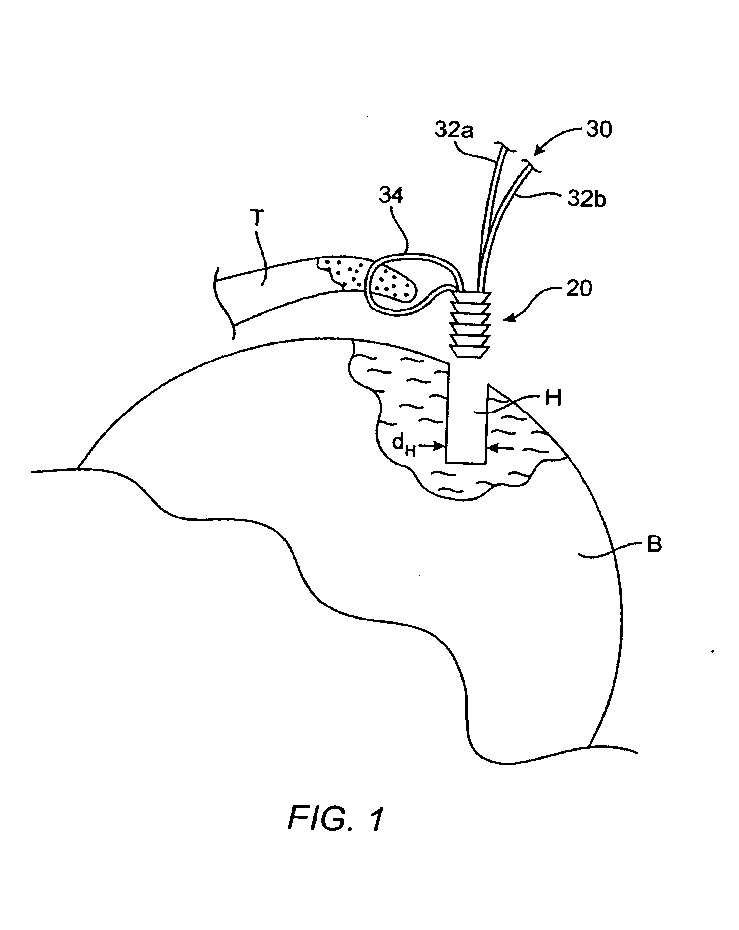
[0173]FIG. 1 is an illustrative schematic of a bone and tissue interface. Tissue T has a torn end and it is desirable to secure the torn end to a section of bone B. In a first step, hole H having diameter dH may be drilled in bone B, as depicted, using generally known bone drilling techniques.

[0174]Bone anchor member 20 may secure tissue T to bone B. Bone anchor member 20 may be used in conjunction with a length of suture 30. Suture 30 has first end 32a and second end 32b. Ends 32a, 32b may be coupled to bone anchor member 20. A central region of suture 30 forms loop 34. Loop 34 may be threaded through a section of tissue T near the torn end of the tissue using generally known threading techniques. In embodiments described herein tissue, hole, and bone refer to T, H and B, respectively, as described in FIG. 1.

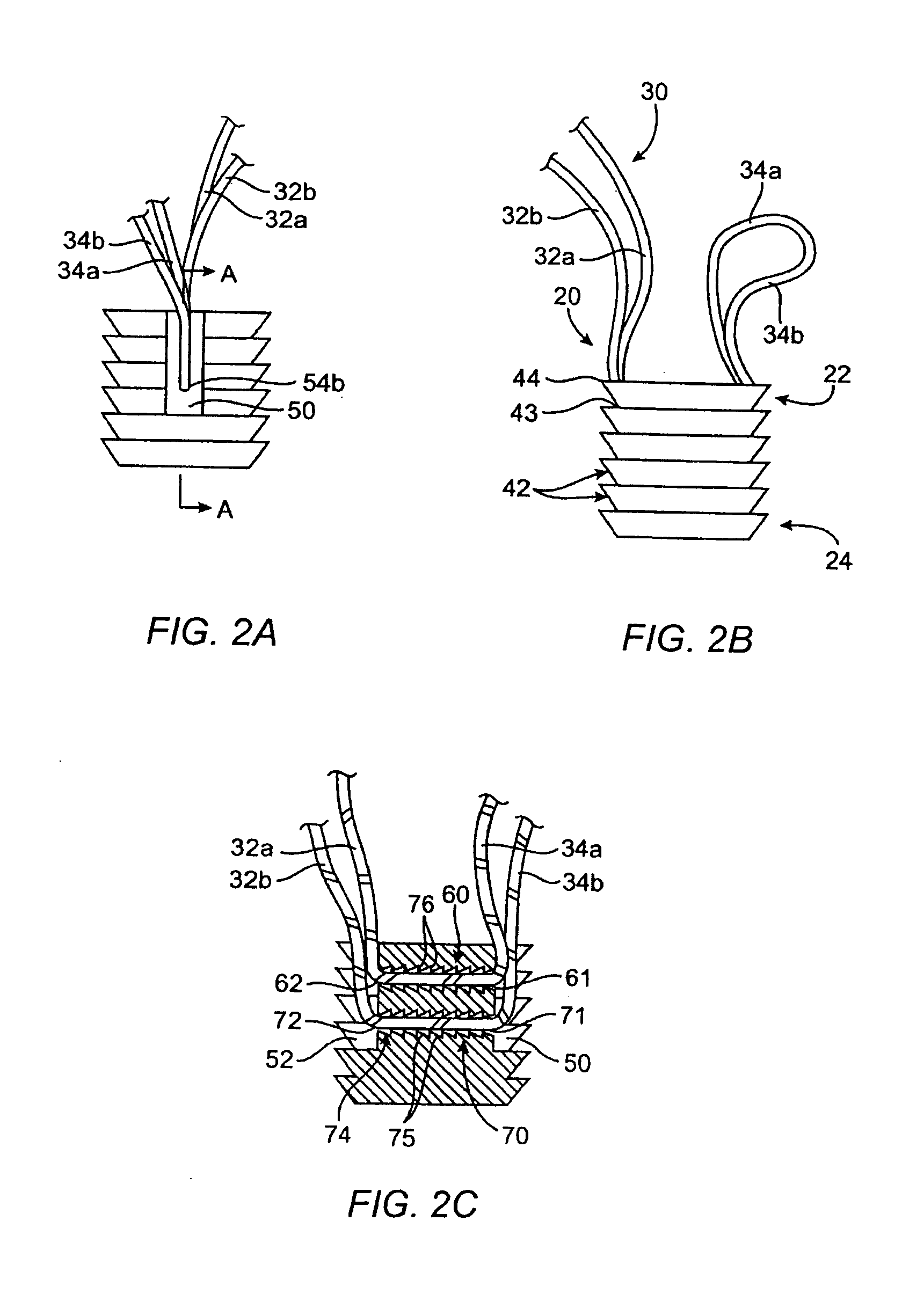
[0175]FIG. 2A is a perspective front view of an embodiment of a bone anchor. FIG. 2B is a perspective side view of the bone anchor along line A-A shown in FIG. 2A. FIG. 2C is a...


PUM


Abstract

Systems, apparatuses and methods for securing tissue to bone using tack anchors, bone anchoring systems are described. The tack anchor may include a body and a securing element. The body may include one or more compressible flanges, an opening and, a cavity. The cavity may include an opening near or proximate the flanges, and be configured to receive a suture. The securing element may be configured to slide into the opening of the body to secure a portion of one or more sutures in the cavity such that the ends of the sutures are accessible through the cavity opening. In some embodiments, tack anchor tool for insertion of a tack anchor into tissue and / or bone is described.

Description

REFERENCE TO PENDING PRIOR PATENT APPLICATION[0001]This patent application claims benefit of pending prior U.S. Provisional Patent Application Ser. No. 60 / 905,216, filed Mar. 5, 2007 by Gary S. Fanton et al. for TACK ANCHOR SYSTEMS, BONE ANCHOR SYSTEMS, AND METHODS OF USE (Attorney's Docket No. 6008-01100), which patent application is hereby incorporated herein by reference.BACKGROUND[0002]1. Field of the Invention[0003]The present invention relates to systems, methods and apparatus for securing tissue to bone. More particularly, the invention relates to apparatus and methods for facilitating the attachment of tissue to bone using tack anchoring systems and / or a bone anchoring system. The present invention also relates to a tack anchor tool instrument for inserting a tack anchor system into tissue and / or bone.[0004]2. Description of the Related Art[0005]Many attempts have been made to provide devices that allow the arthroscopic securing of torn tissue to a human bone. For example, n...

Claims


Application Information

Patent Timeline
Patent Type & Authority Applications(United States)
IPC IPC(8): A61B17/10A61B17/04
CPCA61B17/0401A61B17/0469A61B17/0487A61B2017/0409A61B2017/0427A61B2017/0414A61B2017/0417A61B2017/2918A61B2017/0412
Inventor FANTON, GARY S.KRUMME, JOHN
Owner HOWMEDICA OSTEONICS CORP
Why Eureka
Try Eureka