Direct grease injection for large open gearing

a technology of grease injection and gearing, which is applied in the direction of machines/engines, collapsible antennas, hoisting equipment, etc., can solve the problems of gear drive wear, waste and mess, troublesome and messy lubrication with grease or another suitable lubricant, etc., to reduce wear, reduce mess, and reduce the effect of mess

Active Publication Date: 2008-11-13
RAYTHEON CO
View PDF11 Cites 33 Cited by
  • Summary
  • Abstract
  • Description
  • Claims
  • Application Information

AI Technical Summary

Benefits of technology

[0007]It is a further object of this invention to provide such a method which minimizes the mess associated with prior lubrication schemes.
[0008]It is a further object of this invention to provide such a method which reduces wear.
[0009]It is a further object of this invention to provide such a method which eliminates the need to manually apply the lubricant.
[0010]The subject invention results from the realization that a more effective, automatic, less messy, and more precise lubrication of a bull, girth, slew drive, final drive, or other exposed gears is effected by configuring the gear which drives these gears with radial internal channels extending to the periphery of the drive gear to provide a lubricant such as grease to where the drive gear teeth mesh with the teeth of the bull, girth, slew drive, or final drive gear.

Problems solved by technology

Lubricating such gear drives with grease or another suitable lubricant is troublesome and messy.
Prior attempts at automatic grease applications resulted in waste and mess.
When lubrication is ineffective, the result is wear of the gear drive.
Moreover, even when the lubrication effort is effective, the result can be a waste of grease and / or grease contamination of adjacent equipment which, in the case of an antenna on board a ship, cannot be tolerated.

Method used


Image

  • Direct grease injection for large open gearing
  • Direct grease injection for large open gearing
  • Direct grease injection for large open gearing

Examples


Embodiment Construction

[0029]Aside from the preferred embodiment or embodiments disclosed below, this invention is capable of other embodiments and of being practiced or being carried out in various ways. Thus, it is to be understood that the invention is not limited in its application to the details of construction and the arrangements of components set forth in the following description or illustrated in the drawings. If only one embodiment is described herein, the claims hereof are not to be limited to that embodiment. Moreover, the claims hereof are not to be read restrictively unless there is clear and convincing evidence manifesting a certain exclusion, restriction, or disclaimer.

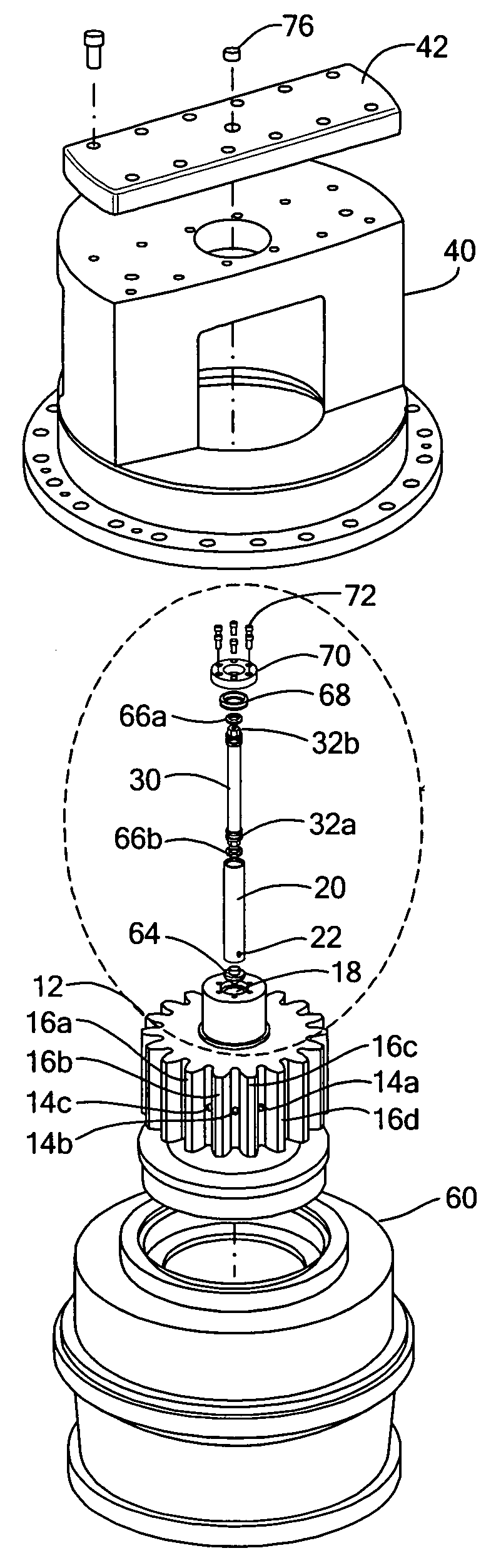
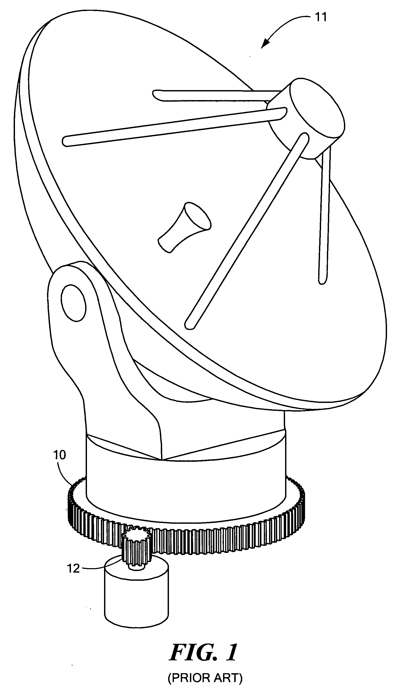
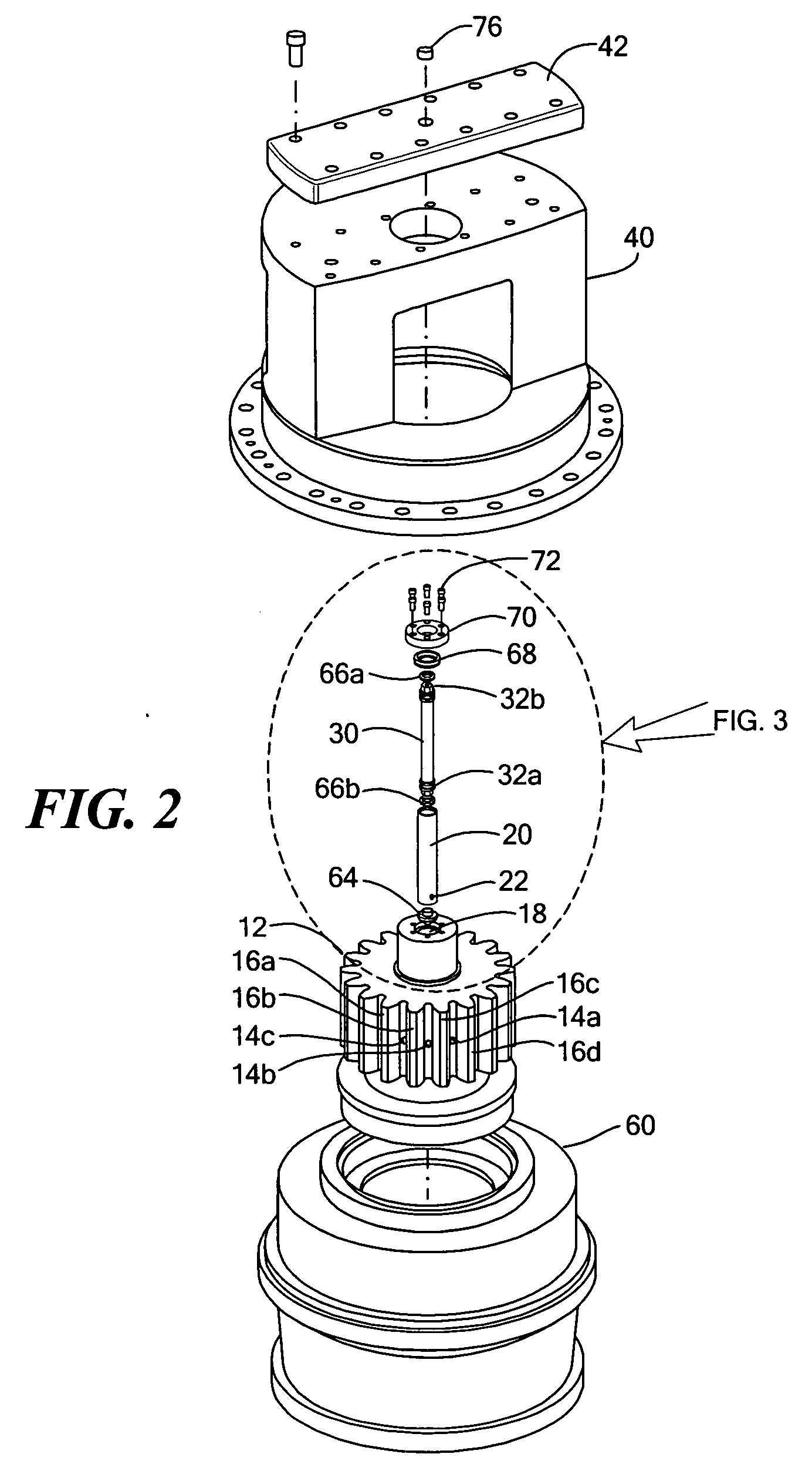
[0030]FIG. 1 schematically shows final drive gear 10 of rotating antenna structure 11. An example of antenna structure 11 includes Raytheon's (Waltham, Mass.) steerable radar systems. But, gear 10 may be any open gear such as a bull gear, girth gear, slew drive gear, and the like. Gear 10 is driven by drive gear 12 which, i...


PUM


Abstract

A drive gear includes a plurality of internal radial channels extending between the axial bore and the periphery of the gear, and an axial bore includes a lubricant distribution structure therein to provide lubrication where the teeth of the drive gear mesh with the teeth of a gear driven by the drive gear.

Description

GOVERNMENT RIGHTS[0001]This invention was made with U.S. Government support under Contract No. N00024-04-C-5340. The U.S. Government may have certain rights in the subject invention.FIELD OF THE INVENTION[0002]This subject invention relates to gears and gear lubrication.BACKGROUND OF THE INVENTION[0003]Some large gear drives are exposed to the environment and are not lubricated by circulating oil. Examples includes bull gears, girth gears, slew drive gears used for cranes, excavators, and other heavy equipment, gears used to rotate draw bridges, gears for ball mills, and also the final drive gear for steerable radar antennas on ships. Typically, a smaller pinion gear drives the large exposed gear.[0004]Lubricating such gear drives with grease or another suitable lubricant is troublesome and messy. Sometimes, a brush is used to manually and periodically apply grease to the gear drive. Prior attempts at automatic grease applications resulted in waste and mess. When lubrication is inef...

Claims


Application Information

Patent Timeline
Patent Type & Authority Applications(United States)
IPC IPC(8): F16H57/04
CPCF16H57/0426F16H57/0431F16H57/0495Y10T74/19888Y10T74/19995Y10T74/19991Y10S384/905
Inventor SALMELA, GORDON O.CREONTE, JOSEPH A.
Owner RAYTHEON CO
Why Eureka
Try Eureka