
Grating system and sidewall seal arrangement for oscillating grate stoker

a technology of oscillating grate and sidewall seal, which is applied in the direction of solid fuel combustion, lighting and heating apparatus, chemistry apparatus and processes, etc., can solve the problems of excessive vibration, inability to retrofit an existing boiler, and inability to transmit excessive vibration

Inactive Publication Date: 2008-11-13
RILEY STOKER
View PDF30 Cites 9 Cited by
  • Summary
  • Abstract
  • Description
  • Claims
  • Application Information

AI Technical Summary

Benefits of technology

[0009]The present invention relates to a seal arrangement for use between an oscillating grate of a stoker apparatus and a boiler with which it is used. The seal arrangement presented herein facilitates vibration isolation between the vibrating grate and the boiler, while effectively inhibiting release of combustion gases through the seal.

Problems solved by technology

This arrangement adds cost, results in excess transmission of vibrations, and results in failure due to fatigue in the water pipes.
In many vibrating grate systems excessive vibration is coupled to the boiler and the surrounding structure.
This occurs, particularly when the grate is not effectively counter-balanced or isolated from the boiler.
Although this arrangement may be suitable, such an arrangement may not lend itself easily to retrofit of an existing boiler.
Further, the protrusion provided on the boiler feed water supply line 119 is not easily replaceable.
Accordingly, if it is abraded by moving fuel, major repairs may be necessary, resulting in unnecessary boiler down time.

Method used


Image

  • Grating system and sidewall seal arrangement for oscillating grate stoker
  • Grating system and sidewall seal arrangement for oscillating grate stoker
  • Grating system and sidewall seal arrangement for oscillating grate stoker

Examples


Embodiment Construction

[0036]Reference will now be made in detail to the present preferred embodiments of the invention, an example of which is illustrated in the accompanying drawings. The method and corresponding steps of the invention will be described in conjunction with the detailed description of the system.

[0037]The present application includes improvement on existing related technology, as exemplified by U.S. Pat. No. 6,220,190 issued Apr. 24, 2001, which patent is hereby incorporated by reference in its entirety.

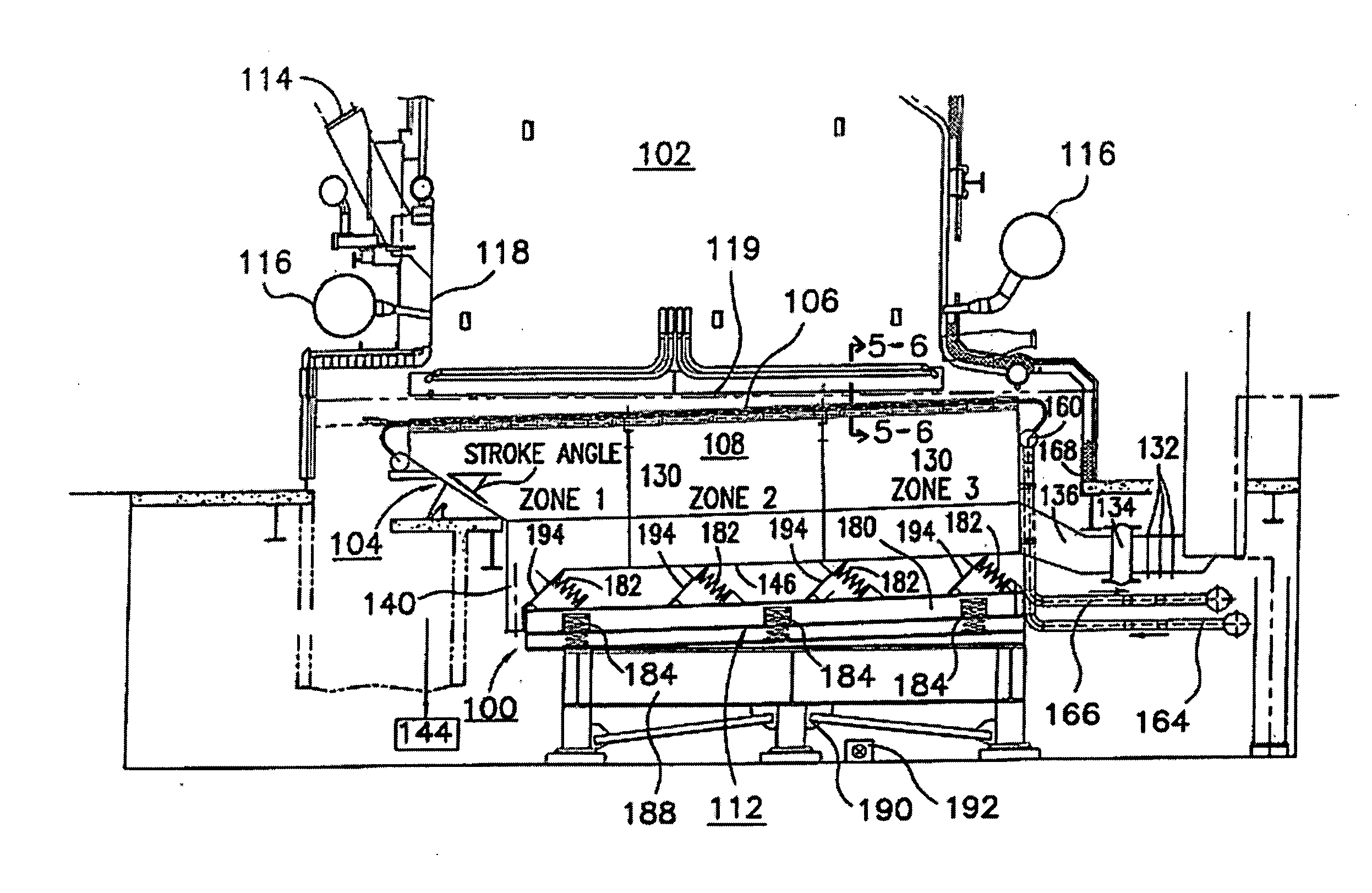
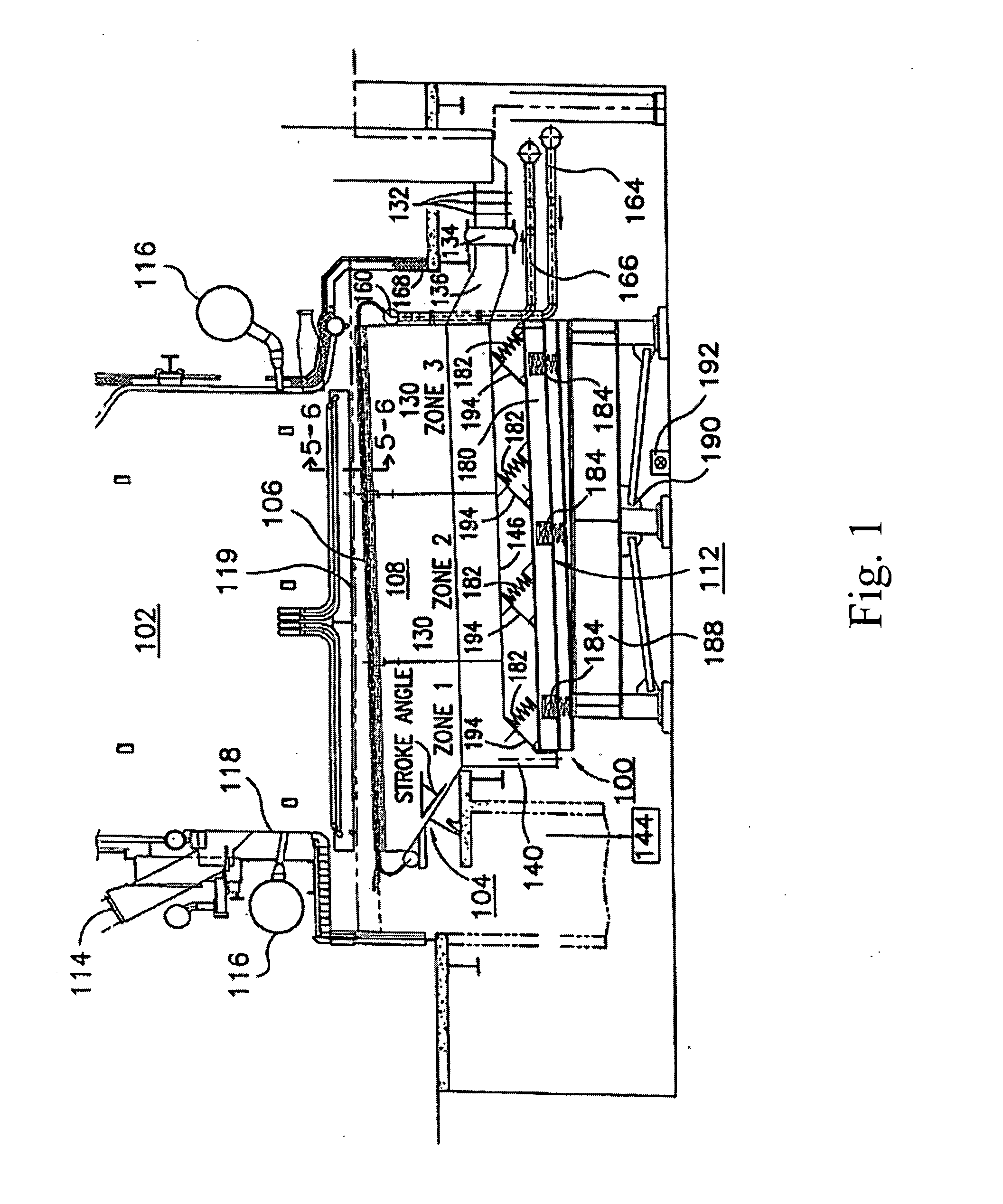
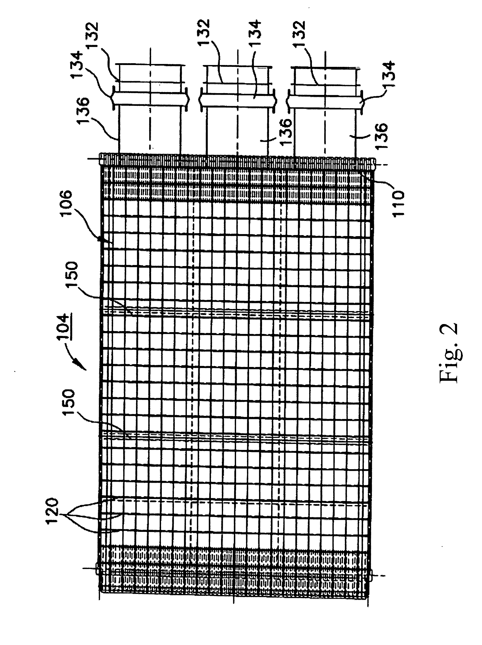
[0038]FIG. 1 illustrates a vibrating grate system generally designated by reference character 100 and arranged in accordance with the present invention in a boiler 102. In accordance with the invention, the grate system 100 includes a grate unit generally designated 104. Among its primary components, the grate unit 104 has upper and lower surfaces and can include an air plenum 108 and a plurality of water cooling tubes 110. The grate unit 104, in conjunction with the air plenum 108 is an ...


PUM


Abstract

The invention includes a grate system for a boiler. The grate system includes a grate unit and a side header guard. The grate unit supports fuel during combustion thereof, and has an upper surface, a lower surface, and upturned lateral edges. The side header guard is arranged along a side wall of the boiler and has upwardly and downwardly projecting fin portions. The upwardly projecting fin portion is adapted and configured to extend over and protect the boiler side wall from abrasion by fuel. The downwardly projecting fin portion is adapted and configured to extend over the upturned lateral edge of the grate unit, inhibiting passage of fuel therebetween.

Description

BACKGROUND OF THE INVENTION[0001]1. Field of the Invention[0002]The present invention generally relates to boiler systems, and more particularly to a water-cooled oscillating grate system for a boiler for use with solid fuels.[0003]2. Description of Related Art[0004]Large-scale boilers are used in industrial processes and in power generation, among other applications. Fuel is fed into such boilers, and handled by an automatic or remotely operated grating system. Such gratings are typically movable or vibrating to facilitate combustion by mixing solid fuel held thereon. The gratings for stokers used in large-scale boiler systems are formed of multiple sections approximately 2 meters in width. Typically, steep walled hoppers are required underneath the gratings to collect ash siftings that fall through openings between grate sections. Also, multiple water pipes typically project from each end of the grate to stationary water headers. This arrangement adds cost, results in excess trans...

Claims


Application Information

Patent Timeline
Patent Type & Authority Applications(United States)
IPC IPC(8): F23B99/00
CPCF23H1/02F23H9/04F23H17/02F23H17/08F23H2900/03021F23H2900/09041B07B1/42B07B1/44
Inventor SUND, JOHNPACE, LARRYTOUPIN, KEVIN
Owner RILEY STOKER
Learn More