Vehicle damper of variable damping force

a variable damping and damping force technology, applied in the direction of liquid based dampers, springs/dampers, shock absorbers, etc., can solve the problems of slow response speed of the valve b>505/b>, inability to appropriately control the valve, and difficulty in imparting flexible movement to the valve, so as to improve the responsiveness of the single-cylinder damper, and improve the responsiveness of the valv

Inactive Publication Date: 2008-11-13
HONDA MOTOR CO LTD
View PDF4 Cites 12 Cited by
  • Summary
  • Abstract
  • Description
  • Claims
  • Application Information

AI Technical Summary

Benefits of technology

[0019]The valves and the electromagnetic solenoid are provided to the piston. Thus, the responsiveness of the single-cylinder damper can be improved.
[0020]Preferably, the cylinder comprises an inner cylinder in which the piston makes a sliding movement, and an outer cylinder disposed coaxially with and externally of the inner cylinder, and the valves and the electromagnetic solenoid are placed in communication ducts provided either at an end of the inner cylinder or between the inner cylinder and the outer cylinder. Thus, responsiveness of the valves can be improved in a multi-cylinder damper as well.
[0021]Desirably, the magnetic flux delivery member is disposed at a position that faces the opening / closing ends of the opening / closing parts when the opening / closing parts are in the open state. Therefore, a strong magnetic flux is created between the magnetic flux delivery member, the valves, and the piston when the valves are in the open state. As a result, highly responsive valve control can be achieved.
[0022]In a preferred form, the supporting parts are provided in the axial center of the piston. Therefore, the valves can be easily supported on the piston.
[0023]In a desired form, the supporting parts are provided in proximity to the external periphery of the piston. Therefore, a longer distance can be set between the opening / closing parts and the supporting parts in comparison with cases in which the supporting parts are provided in the axial center of the piston.
[0024]The opening / closing parts and the supporting parts may be provided in areas on opposite sides of a straight line passing diametrically of the piston. Thus, a longer distance (span) can be set (sufficiently worked) between the opening / closing parts (points of force) and the supporting parts (fulcra). The durability of the valves can be thereby improved and highly responsive valves with reduced opening and closing force can be obtained. As a result, satisfactory control can be exerted over the damping force of the vehicle damper of variable damping force.

Problems solved by technology

Therefore, it has been difficult to impart flexible movement to the valve 505.
Therefore, the valve 505 has had a slow response speed, and it has not been possible to appropriately control the valve 505.

Method used


Image

  • Vehicle damper of variable damping force
  • Vehicle damper of variable damping force
  • Vehicle damper of variable damping force

Examples


first embodiment

[0036]A damper of variable damping force according to the present invention will now be described with reference to FIGS. 1 through 6.

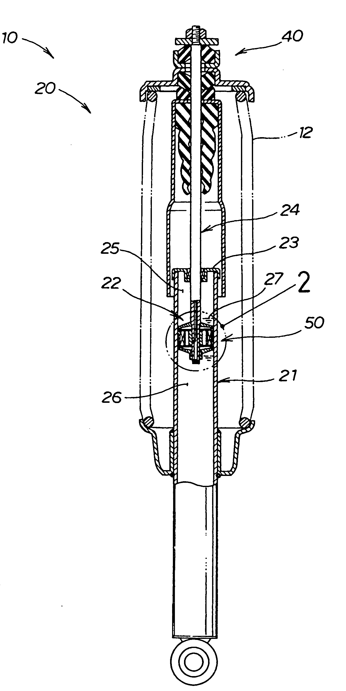
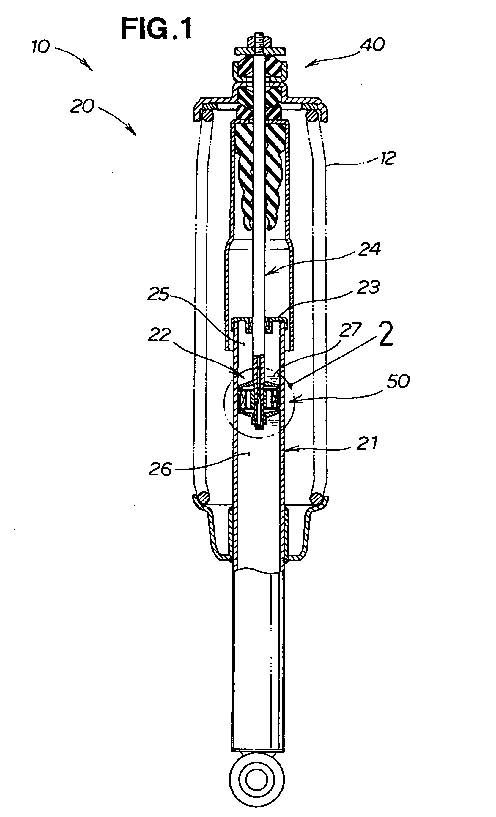
[0037]A damper unit 10 is composed of a damper 20 of variable damping force (vehicle damper of variable damping force) and a coil spring 12, as shown in FIG. 1.

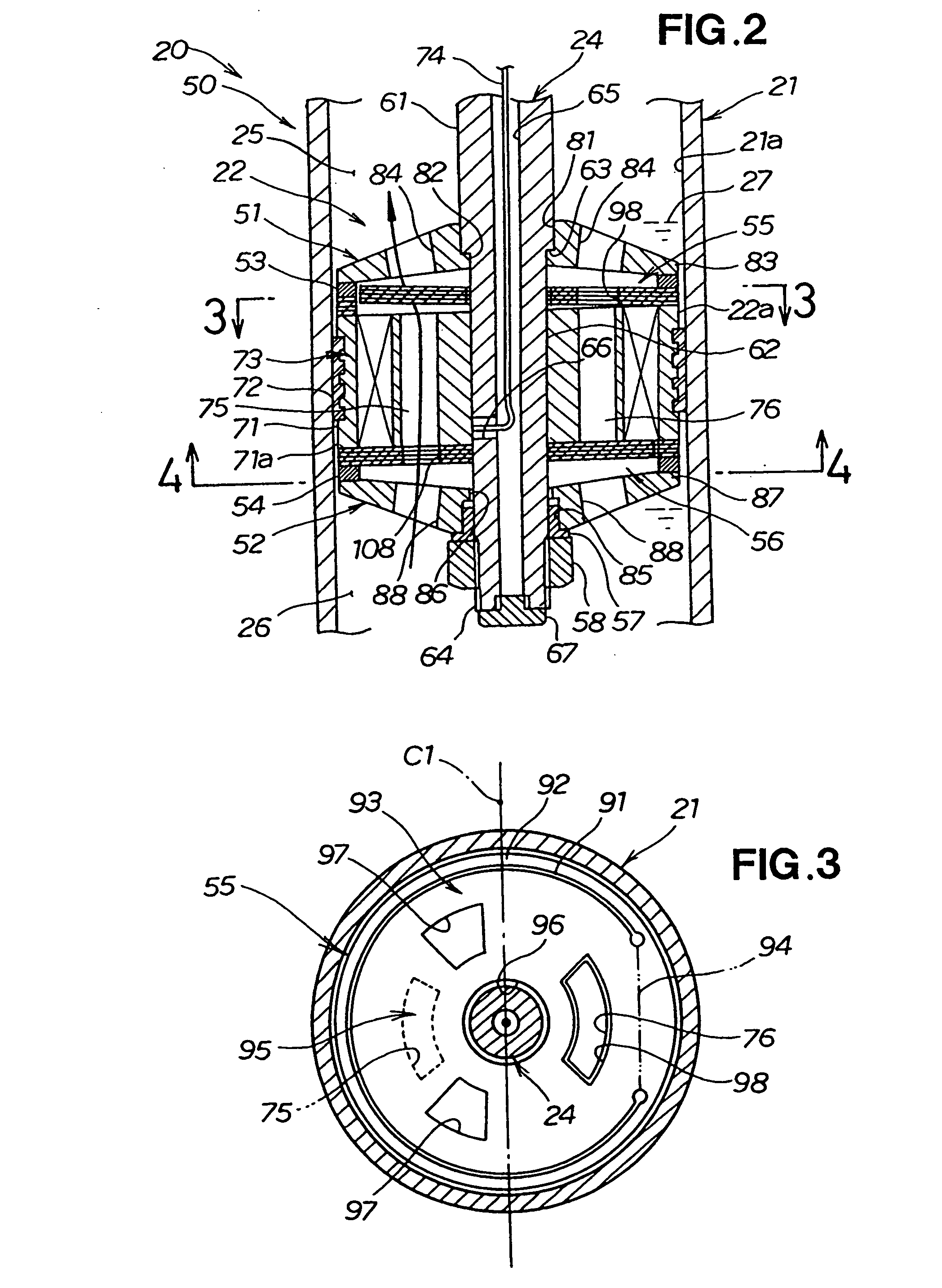
[0038]The damper 20 of variable damping force is composed of a tubular cylinder 21, a piston 22 that is slidably mounted within the cylinder 21 and that divides the cylinder 21 interior vertically into two chambers, a rod 24 that is attached to the piston 22 and that protrudes from one end of the cylinder 21 via a rod guide 23, and damper oil 27 that is hermetically sealed inside the cylinder 21 and that flows through the two chambers (upper chamber and lower chamber) 25, 26 via ports 75, 76 (see FIG. 2) in the piston 22, wherein the lower end of the damper is fixed to a suspension arm (not shown), and the upper end is fixed to a side of a vehicle body via an upper mount 40.

[0039]A piston assem...

second embodiment

[0086]FIG. 7 shows a damper 220 of variable damping force according to the

[0087]Similar to the damper 20 of variable damping force according to the first embodiment, the damper 220 of variable damping force according to the second embodiment is composed of a tubular cylinder 221, a piston 222 that is slidably mounted within the cylinder 221 and that divides the cylinder 221 interior vertically into two chambers, a rod 224 that is attached to the piston 222 and that protrudes from one end of the cylinder 221 via a rod guide 23 (FIG. 1), and damper oil 227 that is hermetically sealed inside the cylinder 221 and that flows through the two chambers (upper chamber and lower chamber) 225, 226 via ports 275, 276, wherein the lower end of the damper is fixed to a suspension arm (not shown), and the upper end is fixed to a side of a vehicle body via an upper mount (not shown).

[0088]The piston 222 is composed of a piston body 271 attached to an external screw 264 of the rod 224, an upper push...

third embodiment

[0099]In other words, in the damper 320 of variable damping force since the supporting parts 392, 396 of the upper and lower valves 355, 356 are positioned in the center of the piston body 71, the valves 355, 356 can be easily supported on the piston body 71.


PUM


Abstract

A vehicle damper of variable damping force including a cylinder, a piston and valves is disclosed. The valves have opening/closing parts and supporting parts. The opening/closing parts and the supporting parts are positioned separately so that a sufficient distance is obtained. Lengthening the distance from the supporting parts to the opening/closing parts makes it possible to reduce the opening and closing force of the opening/closing parts and to obtain highly responsive valves.

Description

FIELD OF THE INVENTION[0001]The present invention relates to a vehicle damper of variable damping force wherein valves disposed in a flow passage are opened and closed by magnetic attraction of an electromagnetic solenoid to thereby vary the damping force of the damper.BACKGROUND OF THE INVENTION[0002]In this type of damping force variable damper, oil flows through ports formed in a piston, and damping force is created by the resistance when the oil flows. To vary the damping force, it is common to vary the amount of oil flowing through the ports to change the damping force.[0003]An example of this type of vehicle damper of variable damping force is a damper in which an electromagnet is used to suitably open and close the ports and the damping force of the damper is varied, as is disclosed in Japanese Patent Application Post-Exam Publication No. 1-47323 (JP 01-047323 B), for example.[0004]The damper of variable damping force of JP 01-47323 B will be described below with reference to...

Claims


Application Information

Patent Timeline
Patent Type & Authority Applications(United States)
IPC IPC(8): F16F9/14
CPCF16F9/3485F16F9/464
Inventor NAKAJIMA, KIYOSHITOMARI, TATSUHIROSUKIGARA, TORU
Owner HONDA MOTOR CO LTD
Why Eureka
Try Eureka