Folding machine and printing machine using same

a printing machine and folding machine technology, applied in the field of folding machines and printing machines, can solve the problems of inability to smoothly move the signature at both ends, and inability to accurately fold the signature, etc., to achieve good products, improve folding accuracy, and simple structure

Inactive Publication Date: 2008-11-13
MITSUBISHI HEAVY IND PRINTING & PACKAGING MACHINERY
View PDF3 Cites 10 Cited by
  • Summary
  • Abstract
  • Description
  • Claims
  • Application Information

AI Technical Summary

Benefits of technology

[0022]The present invention has been made in view of the above, and an object of the present invention is to provide a folding machine that has a simple structure and does not substantially require adjustment, and improves the folding accuracy to obtain good products, and to provide a printing machine that uses the folding machine.

Problems solved by technology

However, the signature holding force by the conveyance belts is large, and signature may not be smoothly moved.
Further, if the signature holding force by the conveyance belts is slightly imbalanced, the movement amounts of the signature at the both ends vary.
Then, the signature may not be accurately folded in two, and the accuracy of the folding may be decreased.
Due to the above-described problems, the quality of the signature may be significantly reduced, and troubles may occur in folding in downstream folding or alignment processes.
However, the adjustment is difficult, and sufficient results have not been obtained.
However, the device discussed in document 1 is complicated in the structure, and the folding machine is large.
Further, it is substantially difficult to adjust the speeds of each conveyance belt to appropriate speeds corresponding to change in paper quality, paper thickness, the number of pages, and the like.
Also, the device discussed in document 2 is complicated in the structure of the chopper folding machine, and it is substantially difficult to adjust the speeds of the speed-reduction conveyance belt to appropriate speeds corresponding to change in paper quality, paper thickness, the number of pages, and the like.
On the contrary, if the space between the pair of vertically arranged conveyance belts is too narrow, it is substantially difficult that the device adjusts the space corresponding to the change in paper quality, paper thickness, the number of pages, and the like.

Method used


Image

  • Folding machine and printing machine using same
  • Folding machine and printing machine using same
  • Folding machine and printing machine using same

Examples


first embodiment

[0065]A first embodiment of the present invention is described with reference to FIGS. 1 to 6.

[0066]In the first embodiment, the present invention is applied to an opposed blanket type web press that perform multicolor printing on both sides of a web.

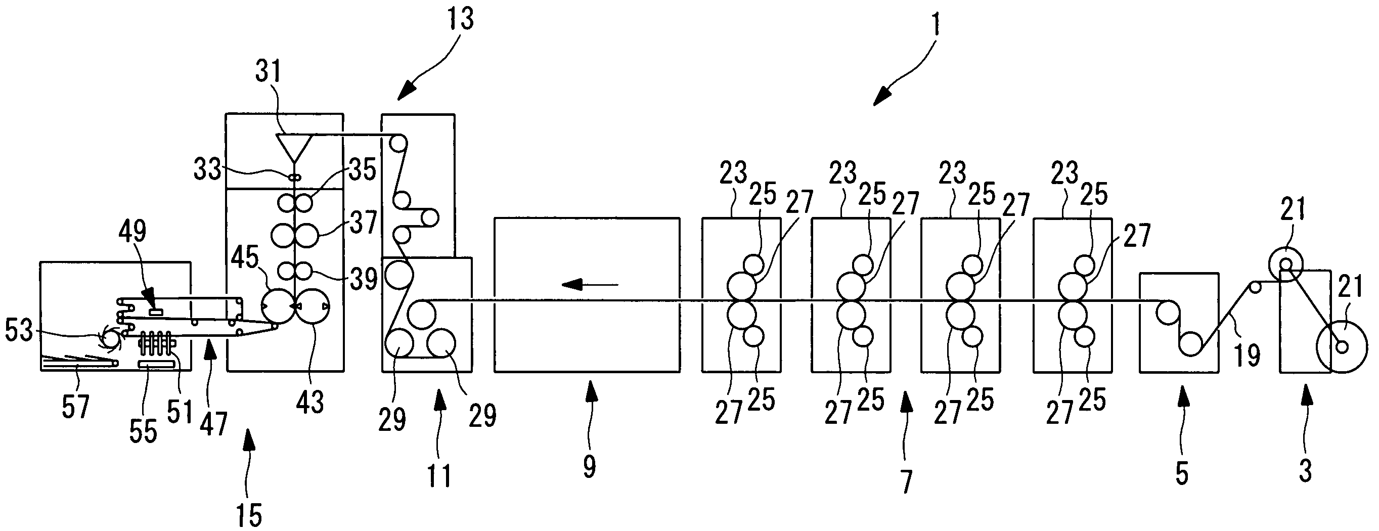
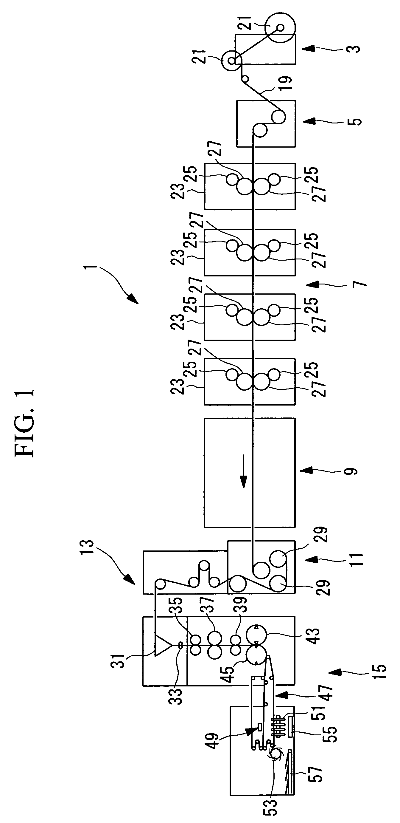
[0067]FIG. 1 is a front elevation view illustrating a schematic structure of an entire web press (printing machine) 1.

[0068]The web press 1 includes, along a conveyance direction of a web 19, a paper feed device 3, an in-feed device 5, a printing section 7, a drying device 9, a cooling device 11, a web pass section 13, and a folding machine 15.

[0069]The paper feed device 3 supplies a web 19, and holds two paper rolls 21 that are formed of rolled webs 19.

[0070]While the paper is supplied from one paper roll 21, the other paper roll 21 is installed to prepare for paper splicing. When the web 19 of the one paper roll 21 comes to an end, the web 19 is spliced to the web 19 of the other paper roll 21. While the web 19 is supplied from the ot...

example

[0173]A printing was performed using the POLYBELT® Type KCS-350 (width: 15 mm, thickness: 1.1 mm) produced by Nitta Corporation having a configuration shown in FIG. 4 for the lower conveyance belt 65 and the upper conveyance belt 75 in the printing device LITHOPIA MAX AY1-700 produced by Mitsubishi Heavy Industries, Ltd., and 16 pages of A-4 sized chopper signatures 60 were obtained.

[0174]A coefficient of static friction of the lower conveyance surface 103 and the upper conveyance surface 105 to a surface formed of an iron material was set to 0.2 or more and less than 0.3.

[0175]For the web 19, two types of coated paper of basis weight of 49 g / m2 and 73 g / m2 were used. A printing speed, that is, the number of rotations of the plate 25 was varied to 600, 650, 700, 750, and 800 rpm. Under the conditions, signatures 59 were examined for any rip formed due to contact with the stopper 87 (such a rip hereinafter referred to as a “contact rip”).

second embodiment

[0184]Now, the web press 1 according to a second embodiment is described with reference to FIG. 8.

[0185]The second embodiment differs from the first embodiment only in structures of the holding force increasing sections. Accordingly, in the second embodiment, the different point is mainly described, and the descriptions of the same parts as the above-described first embodiment are omitted.

[0186]To the same members as those in the first embodiment, the same reference numbers are applied.

[0187]In the second embodiment, the bent section (plate-like member) W in the upstream side of the chopper table 85 is provided in the upstream side, for example, the bent section W is extended to a point near the upper guide roller 81 of the upstream side.

[0188]The bent section W may have a predetermined curvature, or, gradually varying curvatures.

[0189]Unlike the first embodiment, the nip roller 71 is not used, but the convex section T that protrudes upward is formed on the lower conveyance path sec...


PUM

PropertyMeasurementUnit
friction coefficientaaaaaaaaaa
thicknessaaaaaaaaaa
thicknessaaaaaaaaaa

Abstract

A folding machine includes a lower conveyance belt that forms a lower conveyance path section for guiding and conveying a signature by a lower conveyance surface, an upper conveyance belt that forms an upper conveyance path section for guiding and conveying the signature by an upper conveyance surface, a chopper table for guiding the lower conveyance belt, a stopper for aligning a downstream end position of the signature, and a chopper blade for forming a chopper signature. A coefficient of static friction of the lower conveyance surface and the upper conveyance surface to an iron surface is 0.2 or more and less than 0.3, and a nip roller for increasing holding force to the signature between the lower conveyance surface and the upper conveyance surface is provided at a part more upstream side than the stopper by at least a length of the signature.

Description

BACKGROUND OF THE INVENTION[0001]1. Field of the Invention[0002]The present invention relates to a folding machine and to a printing machine that uses the folding machine.[0003]This application is based on Japanese Patent Application No. 2007-122350, the content of which is incorporated herein by reference.[0004]2. Description of Related Art[0005]Conventionally, in a folding machine in a printing machine, a signature is cut and folded in a sheet-shape in an upstream process, and conveyed by a vertically arranged pair of conveyance belts. During the conveyance, if necessary, the signature is folded in two along a conveyance direction by a chopper folding machine.[0006]The signature being conveyed by the conveyance belts comes in contact with a stopper, a tip of the signature is aligned, and pressed downward by a chopper blade that is lowered from above. Thus, the signature is folded in two while being pressed downward, and discharged to a paper discharge conveyer through an impeller ...

Claims


Application Information

Patent Timeline
Patent Type & Authority Applications(United States)
IPC IPC(8): B41F13/64B42C1/00
CPCB65H29/12B65H29/60B65H45/18B65H2404/531B65H2701/1932
Inventor SHICHIJO, KUNIHIROMOTOOKA, MIKIO
Owner MITSUBISHI HEAVY IND PRINTING & PACKAGING MACHINERY
Why Eureka
Try Eureka