Auxiliary Winding for Improved Performance of a Planar Inductive Charging Platform

a technology of inductive charging platform and auxiliary winding, which is applied in the direction of inductance, transformer, transportation and packaging, etc., can solve the problems of incorrect energy transfer and even heating effect in the metallic desk, simple inability to house electronic equipment, and serious hampered energy transfer

Active Publication Date: 2008-11-13
CITY UNIVERSITY OF HONG KONG
View PDF7 Cites 38 Cited by
  • Summary
  • Abstract
  • Description
  • Claims
  • Application Information

AI Technical Summary

Benefits of technology

[0016]The first and second windings may be formed as conductive coils, or may be formed as conductive tracks on one or more printed circuit boards.

Problems solved by technology

As the flux needs to flow horizontally along the upper and lower surfaces, two inherent limitations arise.
Secondly, a similar problem applies to the secondary device that has to pick up to flux (and energy) on the upper surface of the charging platform.
If it is too thick, it simply cannot be housed in the electronic equipment.
If the charging platform is placed on a metallic desk, the AC flux generated in the charging platform may induce currents in the metallic desk, resulting in incorrect energy transfer and even heating effects in the metallic desk.
Two main problems suffered by the charging system of FIG. 5 proposed by Choi et al include: (1) The planar winding of the secondary module must be placed directly on top of the planar winding of the primary unit.
If it is slightly misplaced, the energy transfer will be seriously hampered.
Such high switching frequency leads to high switching loss in the primary inverter circuit, high AC resistance in the PCB copper tracks and more importantly high electromagnetic interference (EMI) emission.
However requiring a multi-layer charging platform increases the complexity of the charging platform undesirably.

Method used


Image

  • Auxiliary Winding for Improved Performance of a Planar Inductive Charging Platform
  • Auxiliary Winding for Improved Performance of a Planar Inductive Charging Platform
  • Auxiliary Winding for Improved Performance of a Planar Inductive Charging Platform

Examples


Embodiment Construction

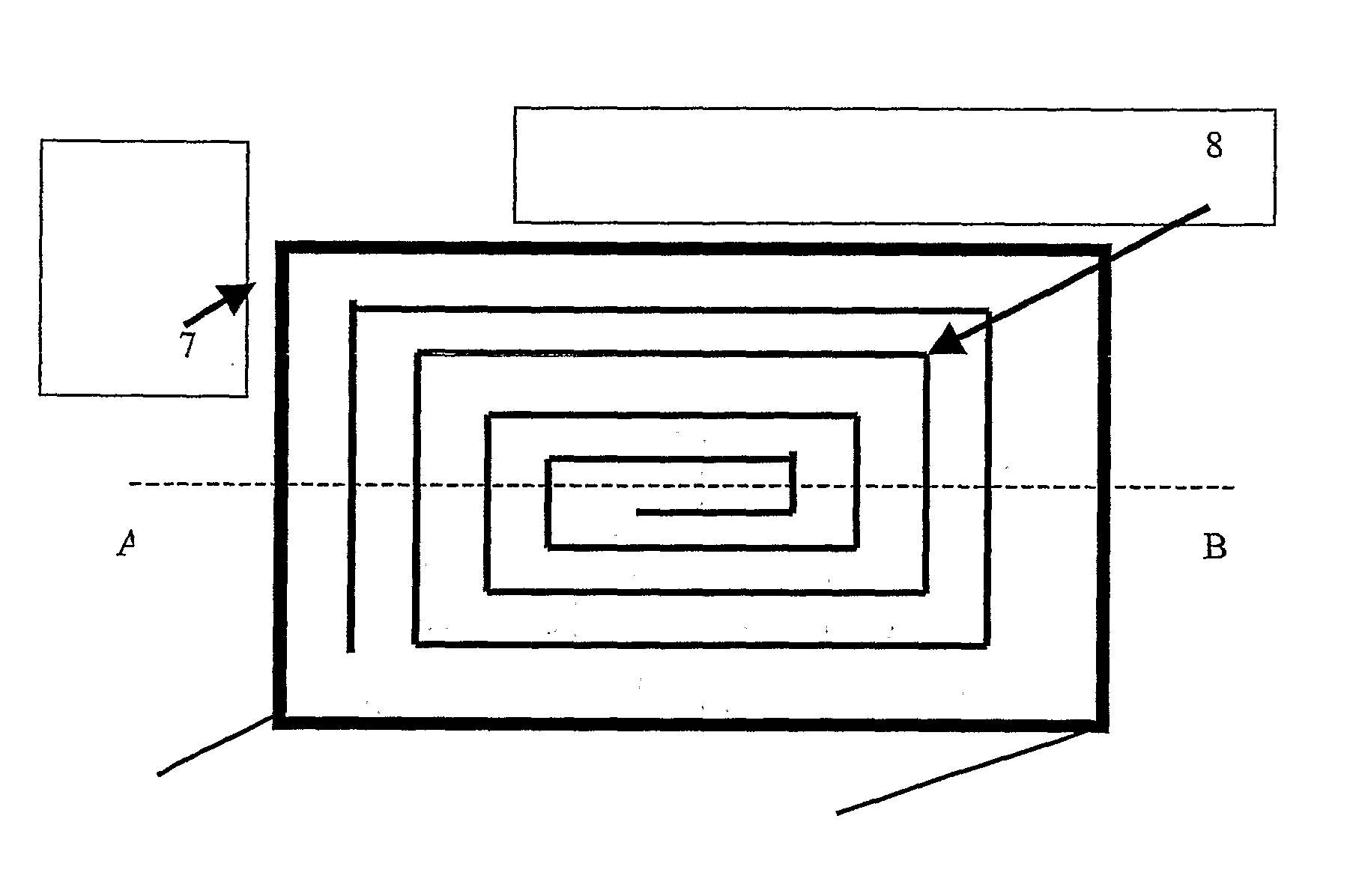
[0031]In order to compensate for the voltage sag phenomenon in the central area of the planar inductive battery charging platform, according to embodiments of the present invention a second auxiliary winding can be placed in the central region of the charging surface in order to boost the electromagnetic flux in that region to compensate for the voltage sag phenomenon.

[0032]FIG. 8A shows a schematic of a planar inductive charging platform based on a single planar primary winding 7 that surrounds a charging surface. In this context the term “primary” is used in the same sense as a transformer, and the energy receiving element will comprises the “secondary”. FIG. 8B shows a schematic of planar inductive charging platform with a second auxiliary winding according to an embodiment of the present invention. As can be seen from FIG. 8B, this embodiment of the present invention includes a first primary planar winding 7 that as in FIG. 8A surrounds the charging surface, but further includes...


PUM

PropertyMeasurementUnit
magnetic fluxaaaaaaaaaa
conductiveaaaaaaaaaa
polarityaaaaaaaaaa

Abstract

A battery charging apparatus comprises an inductive charging platform including a charging surface on which an electrical device to be charged is to be placed, and a first winding for generating lines of magnetic flux generally perpendicular to the charging surface. To compensate for voltage sag caused by a reduction in the flux generated by the first winding, a second winding is located within an area defined by the first winding for generating an auxiliary magnetic flux generally perpendicular to the charging surface.

Description

FIELD OF THE INVENTION[0001]The present invention relates to apparatus for the contactless charging of electrical and electronic devices, and in particular to such apparatus having a planar charging surface with improved charging performance.BACKGROUND OF THE INVENTION[0002]Portable electronic equipment such as mobile phones and personal digital assistants (PDA) usually use rechargeable batteries. Power adaptors (or AC-DC power converters) are traditionally used to charge the batteries in the electronic equipment. Due to the wide range of portable electronic products, many people nowadays have a wide range of power adaptors because there is no standard for charging different types of portable electronic equipment.PRIOR ART[0003]Recently, a number of types of planar inductive charging platforms have been proposed. One example is described in GB2399225A which generates an AC electromagnetic flux 1 with the flux lines flowing “horizontally” along the charging surface 2 as shown in FIG....

Claims


Application Information

Patent Timeline
Patent Type & Authority Applications(United States)
IPC IPC(8): H02J7/00H01F27/28H01F38/14H02J7/02
CPCH01F27/2804H01F38/14H02J7/025H02J50/10H02J7/0042H02J50/005
Inventor HUI, SHU-YUEN RONLIU, XUN
Owner CITY UNIVERSITY OF HONG KONG
Why Eureka
Try Eureka