Miniature Transformers Adapted for use in Galvanic Isolators and the Like

a technology of miniature transformers and isolators, which is applied in the direction of magnets, inductances, magnetic bodies, etc., can solve the problems of difficulty in cost-effective blockage of cross-talk between isolators constructed on silicon substrates using conventional semiconductor fabrication techniques, and the risk of receiving circuits or individuals in contact with those circuits

Inactive Publication Date: 2008-11-13
AVAGO TECH ECBU IP (SINGAPORE) PTE LTD
View PDF43 Cites 119 Cited by
  • Summary
  • Abstract
  • Description
  • Claims
  • Application Information

AI Technical Summary

Problems solved by technology

For example, the transmitting circuit could utilize high internal voltages that would present a hazard to the receiving circuit or individuals in contact with that circuit.
The cost of the semiconductor substrate is a significant fraction of the cost of the isolator.
This is a particularly significant problem when large coils are required to provide the coupling between the transmitter and receiver.
Cross-talk between the isolators constructed on silicon substrates using conventional semiconductor fabrication techniques is difficult to block in a cost-effective manner because of fringe fields generated by one coil being coupled to an adjacent coil.
If the chips are separated by a sufficient distance on the silicon substrate, the cost of the wasted silicon becomes significant.
In addition to the wasted silicon area, devices constructed using conventional silicon integrated circuit fabrication have limitations that are imposed by the design rules of the fabrication line and the limitations as to materials that are allowed on that line.
The thickness of dielectric that is available in conventional CMOS fabrication lines is insufficient to provide this degree of insulation.
However, the materials in question cannot be utilized in many conventional fabrication lines.
Hence, such transformers are not easily, or economically, constructed using silicon-based fabrication techniques.
However, these devices are made one at a time, and hence, lack the economies of scale that are provided by wafer-scale photolithographic techniques and other mass production techniques developed for integrated circuits and the packaging thereof.
However, these dielectric core transformers have insufficient windings and are required to operate at relatively high frequencies because of the lack of a soft ferrite core.

Method used


Image

  • Miniature Transformers Adapted for use in Galvanic Isolators and the Like
  • Miniature Transformers Adapted for use in Galvanic Isolators and the Like
  • Miniature Transformers Adapted for use in Galvanic Isolators and the Like

Examples


Embodiment Construction

[0034]A transformer according to the present invention is constructed by combining a number of component coils to form the primary and secondary windings of the transformer. Each component coil is constructed on an insulating substrate and includes first and second traces that can be generated using conventional photolithographic techniques of the type utilized in making printed circuit boards or semiconductor devices.

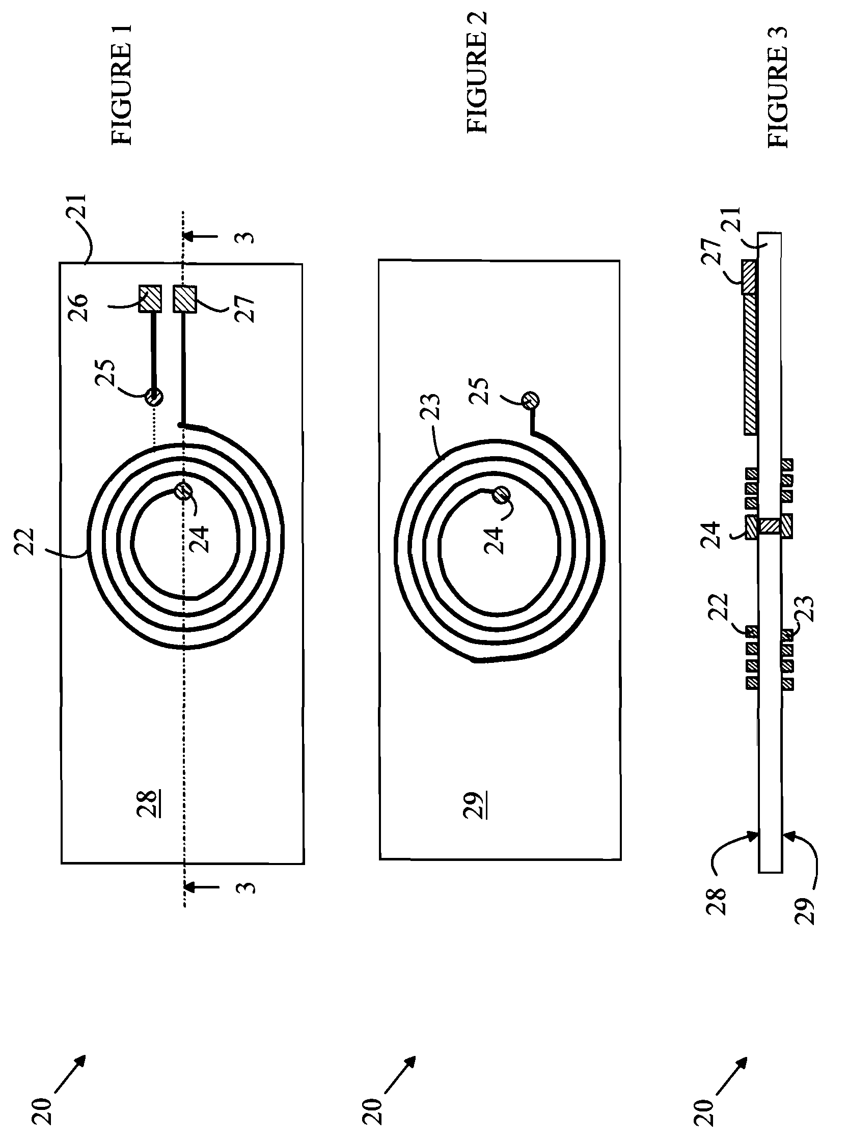
[0035]The manner in which the present invention provides its advantages can be more easily understood with reference to FIGS. 1-3, which illustrate a component coil according to one embodiment of the present invention. FIG. 1 is a top view of component coil 20; FIG. 2 is a bottom view of component coil 20, and FIG. 3 is a cross-sectional view of component coil 20 through line 3-3 shown in FIG. 1. Component coil 20 has a first trace 22 that is deposited on the top surface 28 of an insulating substrate 21, and a second trace 23 that is deposited on the bottom surface 29 ...


PUM

PropertyMeasurementUnit
voltagesaaaaaaaaaa
thickaaaaaaaaaa
magnetic fieldaaaaaaaaaa

Abstract

A component coil for constructing transformers and the transformer constructed therefrom are disclosed. The component coil includes a substrate having an insulating layer of material having top and bottom surfaces. First and second traces are included on the top and bottom surfaces. Each trace includes a spiral conductor. The inner ends of the spiral conductors are connected by a conductor that passes through the insulating layer. The first and second spiral conductors are oriented such that magnetic fields generated by the first and second spiral conductors have components perpendicular to the top surface and in the same direction. The component coils can be used to construct a power transformer or a galvanic isolator.

Description

BACKGROUND OF THE INVENTION[0001]Transformers are often used to transfer information or power between circuits that are operating at different voltages or under different noise conditions. In many circuit arrangements, a logic signal must be transmitted between two circuits that must otherwise be electrically isolated from one another. For example, the transmitting circuit could utilize high internal voltages that would present a hazard to the receiving circuit or individuals in contact with that circuit. In the more general case, the isolating circuit must provide both voltage and noise isolation across an insulating barrier.[0002]One type of galvanic isolator utilizes a transformer based system to isolate the two circuits. The sending circuit is connected to the primary coil of the transformer and the receiving circuit is connected to the secondary coil. The information is transferred by modulating the magnetic field generated in the primary coil. In this arrangement, the sending ...

Claims


Application Information

Patent Timeline
Patent Type & Authority Applications(United States)
IPC IPC(8): H01F5/00H01F27/28H01F7/06H01F27/36
CPCH01F27/2804Y10T29/4902H01F2027/2819H01F2027/2809
Inventor FOUQUET, JULIE E.WARD, CALVIN B.
Owner AVAGO TECH ECBU IP (SINGAPORE) PTE LTD
Why Eureka
Try Eureka