Liquid crystal display device and method of driving liquid crystal display device

a liquid crystal display and display device technology, applied in static indicating devices, instruments, non-linear optics, etc., can solve problems such as difficulty in and achieve the effect of preventing a decrease in contrast and luminance, and high display quality

Inactive Publication Date: 2008-11-13
JAPAN DISPLAY CENTRAL CO LTD
View PDF6 Cites 6 Cited by
  • Summary
  • Abstract
  • Description
  • Claims
  • Application Information

AI Technical Summary

Benefits of technology

[0011]The present invention has been made in consideration of the above-described problem, and the object of the invention is to provide a liquid crystal display device which can prevent a decrease in contrast and luminance and has a high display quality, and a method of driving the liquid crystal display device.
[0014]The present invention can provide a liquid crystal display device which can prevent a decrease in contrast and luminance and has a high display quality, and a method of driving the liquid crystal display device.

Problems solved by technology

In such cases, the transmittance at the time of applying the reverse transition prevention voltage cannot sufficiently be lowered, and it is difficult to prevent a decrease in contrast.
On the other hand, if reverse transition prevention is executed by applying the voltage corresponding to black display in order to obtain the effect of the improvement in visibility, the following problem may occur.

Method used


Image

  • Liquid crystal display device and method of driving liquid crystal display device
  • Liquid crystal display device and method of driving liquid crystal display device
  • Liquid crystal display device and method of driving liquid crystal display device

Examples


Embodiment Construction

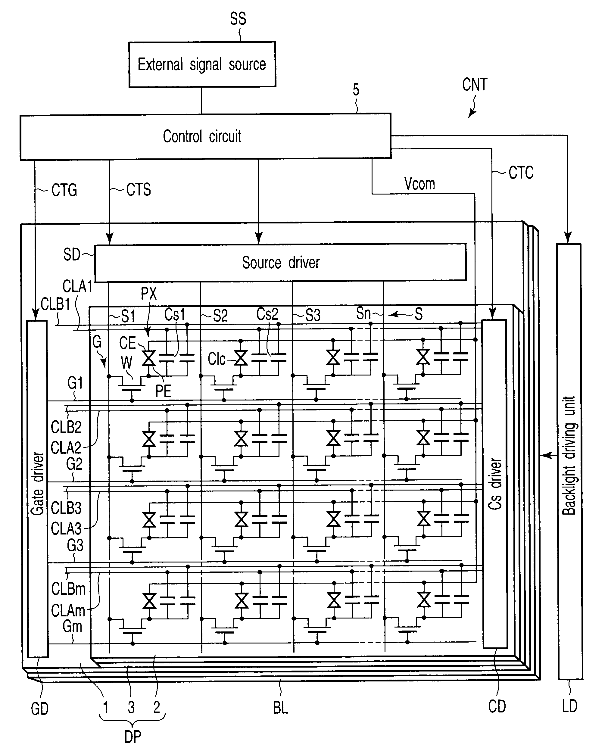
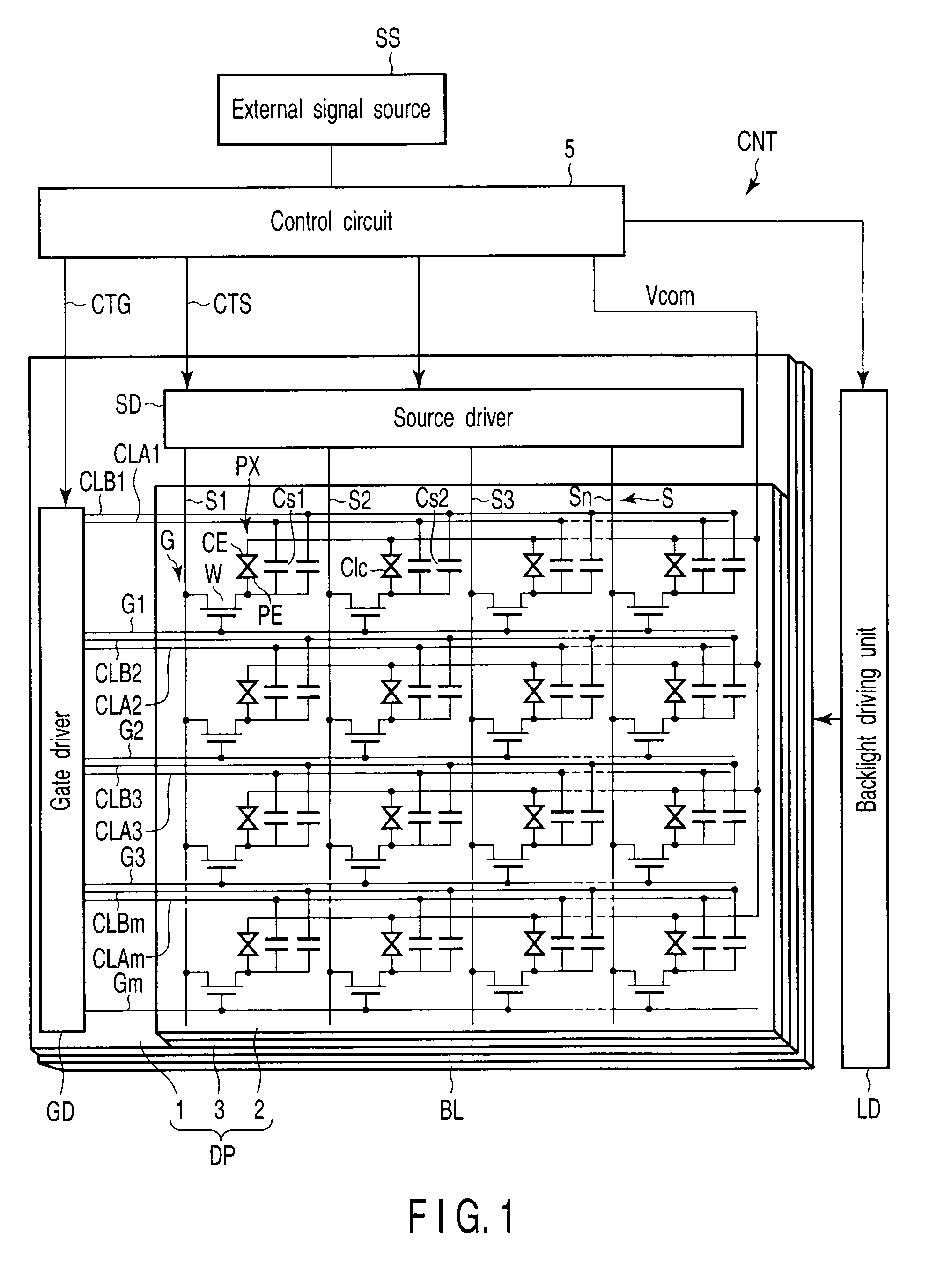
[0022]A liquid crystal display device according to a first embodiment of the present invention will now be described with reference to the accompanying drawings. As shown in FIG. 1, the liquid crystal display device according to this embodiment includes an OCB mode liquid crystal display panel DP, a backlight BL which illuminates the liquid crystal display panel DP, and a controller CNT which controls the liquid crystal display panel DP and backlight BL.

[0023]The liquid crystal display panel DP includes a pair of electrode substrates, i.e. an array substrate 1 and a counter-substrate 2, and a liquid crystal layer 3 which is held between the array substrate 1 and counter-substrate 2. The liquid crystal layer 3 includes, as a liquid crystal material, an OCB mode liquid crystal which is transitioned in advance, for example, from a splay alignment to a bend alignment in order to execute a normally-white display operation.

[0024]In this embodiment, reverse transition of the liquid crystal...


PUM

PropertyMeasurementUnit
liquid crystal voltageaaaaaaaaaa
storage capacitanceaaaaaaaaaa
liquid crystal capacitanceaaaaaaaaaa

Abstract

A liquid crystal display device includes substrates which are opposed to each other, a liquid crystal layer which includes an OCB mode liquid crystal and is held between the substrates, a display section which is composed of display pixels that are arrayed in a matrix, and a driving unit which cyclically charges a reverse transition prevention signal and a video signal in each of the display pixels. The driving unit includes circuits for varying a liquid crystal voltage which is retained in the display pixel after the charging of the reverse transition prevention signal, and a liquid crystal voltage which is retained in the display pixel after the charging of the video signal, thereby making a variation amount of the liquid crystal voltage after the charging of the reverse transition prevention signal greater than a variation amount of the liquid crystal voltage after the charging of the video signal.

Description

CROSS-REFERENCE TO RELATED APPLICATIONS[0001]This application is based upon and claims the benefit of priority from prior Japanese Patent Application No. 2007-122481, filed May 7, 2007, the entire contents of which are incorporated herein by reference.BACKGROUND OF THE INVENTION[0002]1. Field of the Invention[0003]The present invention relates generally to a liquid crystal display device and a method of driving the liquid crystal display device, and more particularly to an active matrix liquid crystal display device and a method of driving the active matrix liquid crystal display device.[0004]2. Description of the Related Art[0005]Compared to, for instance, a TN mode liquid crystal display device, an OCB (Optically Compensated Bend) mode liquid crystal display device has features of higher responsivity and a larger viewing angle. By virtue of these features, the OCB mode liquid crystal display device is most suitable for liquid crystal TV products, the market of which is expected to...

Claims


Application Information

Patent Timeline
Patent Type & Authority Applications(United States)
IPC IPC(8): G02F1/133
CPCG02F1/1395G09G3/3655G09G2300/0491G09G2300/0876G09G2310/06
Inventor FUKAMI, TETSUOTANAKA, YUKIONAKAO, KENJI
Owner JAPAN DISPLAY CENTRAL CO LTD
Why Eureka
Try Eureka