Optical transport network hierarchy for full transparent transport of datacom and telecom signals

a datacom and telecom signal technology, applied in the field of optical networking, can solve problems such as disrupting router-to-router communication, and achieve the effect of increasing the rate and increasing the payload capacity

Active Publication Date: 2008-11-13
CIENA
View PDF6 Cites 38 Cited by
  • Summary
  • Abstract
  • Description
  • Claims
  • Application Information

AI Technical Summary

Benefits of technology

[0011]In yet another exemplary embodiment of the present invention, an Optical Transport Network element configured full transparent transport of datacom and telecom signals includes a tributary interface configured to receive a client signal including one of a plurality of client signal types; a line interface coupled to the tributary interface, wherein the line interface is configured to output the client signal in an Optical Transport Network frame, wherein the client signal is fully transparent within the Optical Transport Network frame, and wherein the Optical Transport Network frame utilizes an increased rate; wherein the Optical Transport Network element utilizes one or more of fixed stuff columns, fixed stuff bytes, a multi-frame stuff byte, and an additional payload byte to bias a justification range required for the client signal in the Optical Transport Network frame. The line interface supports synchronous and asynchronous transparent transport of ±100 parts per million signals.
[0012]The fixed stuff columns are added to a payload area per frame of an Optical Channel Payload Unit as required for coarse adjustments; one to three fixed stuff bytes are added to a column in the payload area as required; the multi-frame stuff bytes are added to one or more frames in a multi-frame as required; and the additional payload byte is added to an Optical Channel Payload Unit overhead as required to increase payload capacity by one byte per frame. Optionally, the Optical Transport Network element is configured to: map the client signal into an Optical Channel Payload Unit; map the Optical Channel Payload Unit into an Optical Channel Data Unit; and map the Optical Channel Data Unit into an Optical Channel Transport Unit. Alternatively, the client signal includes one of a 10 Gigabit Ethernet, a 40 Gigabit Ethernet, a 100 Gigabit Ethernet, a 10 Gigabit Fibre Channel, and a 8 Gigabit Fibre Channel.

Problems solved by technology

Another reason is that some routers use the preamble and 64 B / 66 B code words for proprietary control and data channels and dropping those bits disrupts router-to-router communications.

Method used


Image

  • Optical transport network hierarchy for full transparent transport of datacom and telecom signals
  • Optical transport network hierarchy for full transparent transport of datacom and telecom signals
  • Optical transport network hierarchy for full transparent transport of datacom and telecom signals

Examples


Embodiment Construction

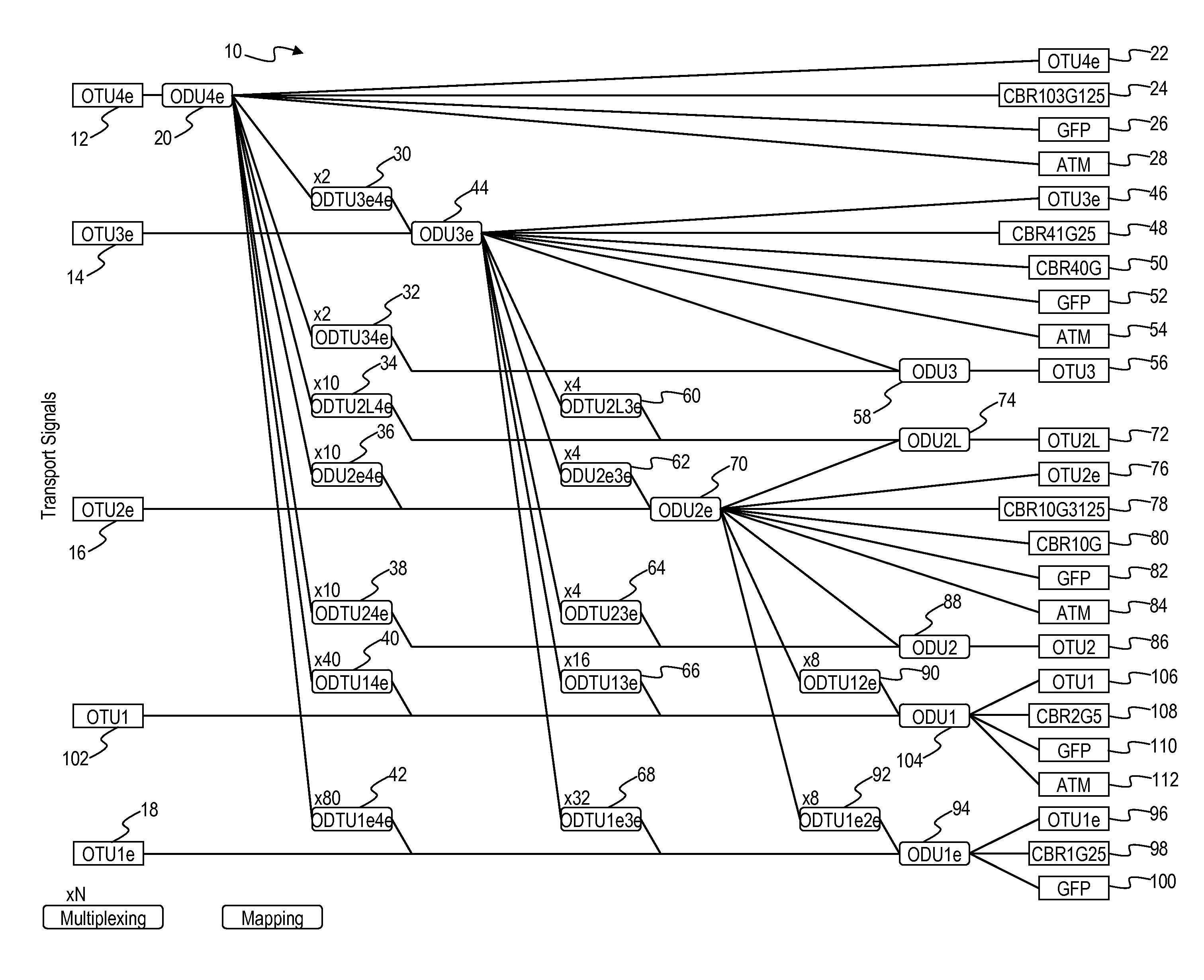
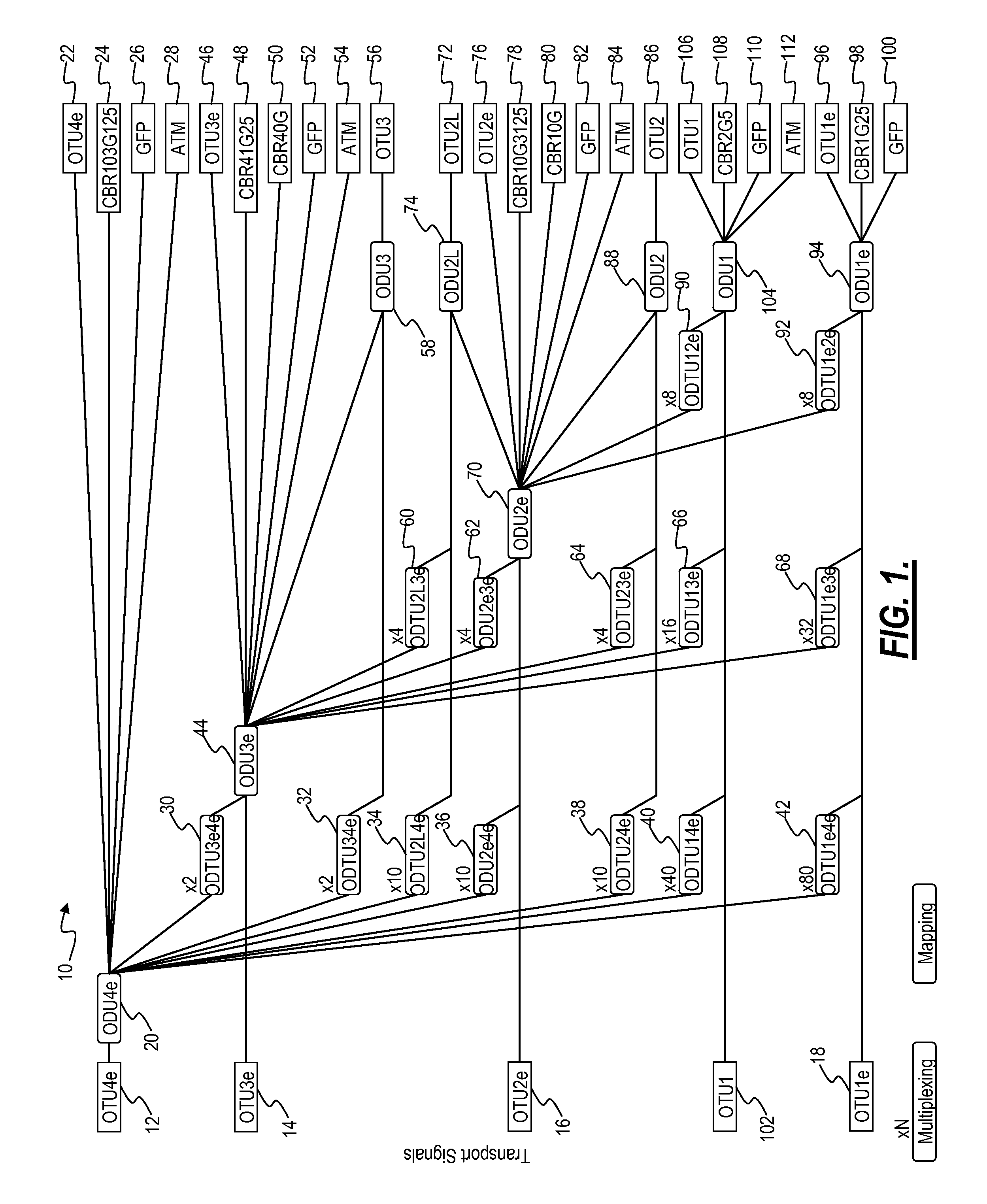
[0023]The present invention provides an Optical Transport Network (OTN) hierarchy that supports full transparency for both Ethernet and Telecom signals. The present invention defines new rates and mapping / multiplexing methods to adapt transparent 10 Gigabit Ethernet (10 GBE) (255 / 238 and 255 / 237) and 10 Gigabit Fibre Chanel (10 GFC) (255 / 237) to Optical Channel Transport Unit-3 (OTU3) at a higher rate. Additionally, the present invention defines new rates and mapping / multiplexing methods to adapt future transparent 100 GBE into an Optical Channel Transport Unit-4-extended (OTU4e) which is an OTU4 at a higher rate to support full transparency.

[0024]The present invention accommodates standard Optical Channel Data Unit-1 (ODU1) mappings into new Optical Channel Data Unit-2-extended ODU2e and Optical Channel Data Unit-3-extended (ODU3e), accommodates standard Optical Channel Data Unit-2 (ODU2) mappings / multiplexing into ODU2e and ODU3e, accommodates standard Optical Channel Data Unit-3 ...


PUM


Abstract

The present invention provides an Optical Transport Network (OTN) hierarchy that supports full transparency for both Ethernet and Telecom signals. The present invention defines new rates and mapping/multiplexing methods to adapt transparent 10 Gigabit Ethernet (10 GBE) (255/238 and 255/237) and 10 Gigabit Fibre Chanel (10 GFC) (255/237) to Optical Channel Transport Unit-3 (OTU3) at a higher rate. Additionally, the present invention defines new rates and mapping/multiplexing methods to adapt future transparent 100 GBE into an Optical Channel Transport Unit-4-extended (OTU4e) which is an OTU4 at a higher rate to support full transparency.

Description

CROSS-REFERENCE TO RELATED APPLICATION(S)[0001]The present non-provisional patent application claims priority to U.S. Provisional Patent Application Ser. No. 60 / 917,490, filed May 11, 2007, and entitled “AN OPTICAL TRANSPORT NETWORK HIERARCHY FOR FULL TRANSPARENT TRANSPORT OF DATACOM AND TELECOM SIGNALS,” which is incorporated in full by reference herein.FIELD OF THE INVENTION[0002]The present invention relates generally to optical networking. More specifically, the present invention provides an Optical Transport Network (OTN) hierarchy that supports full transparency for both Datacom (e.g., Ethernet) and Telecom signals.BACKGROUND OF THE INVENTION[0003]ITU-T defines Optical Transport Network (OTN) as a set of Optical Network Elements connected by optical fiber links, able to provide functionality of transport, multiplexing, routing, management, supervision and survivability of optical channels carrying client signals. Of note, OTN is defined in: ITU-T G.709 “Interfaces for the opti...

Claims


Application Information

Patent Timeline
Patent Type & Authority Applications(United States)
IPC IPC(8): H04B10/20
CPCH04J3/1664H04J2203/0067H04J2203/0089
Inventor MEAGHER, KEVIN S.SUREK, STEVEN A.
Owner CIENA
Why Eureka
Try Eureka