Medical Securing Member Placement System

a technology of medical securing and member placement, applied in the field of medical methods and systems, can solve the problems of coplanar indicia potentially erroneous reflection and unsatisfactory alignment of current devices, and achieve the effects of improving surgeons' ability to perform surgery, improving alignment and prediction, and improving prediction

Inactive Publication Date: 2008-11-13
SMITH & NEPHEW INC
View PDF75 Cites 27 Cited by
  • Summary
  • Abstract
  • Description
  • Claims
  • Application Information

AI Technical Summary

Benefits of technology

[0013]Certain embodiments of the present invention provide methods and systems that allow improved prediction, selection, placement, and insertion of surgical implants and securing members using x-ray and fluoroscopy technology. Certain embodiments provide methods and systems that use imaging devices, implants, and associated drill guide devices to provide improved alignment and prediction of the location and boundary that a securing member will have once inserted. Certain embodiments of the invention provide an implant drill guide and tower with one or more indicators that may be aligned with the holes in the implant under fluoroscopy or other imaging device and may indicate the extents or boundaries of the securing member shaft or body. Certain embodiments involve the use of indicators of varying degrees of radiolucency generating shadows and overlapping images on an imaging device image. Such features improve a surgeon's ability to place, select, and insert an implant and / or a securing member.

Problems solved by technology

In addition, alignment of current devices is often unsatisfactory because it requires cumbersome equipment or indicators.
However, if the two coplanar indicia are themselves misaligned with respect to the implant penetrated by the screw (such as being twisted or bent out of position on the drill guide), these coplanar indicia can potentially erroneously reflect in the radiographic image that the screw is properly aligned in bone.

Method used


Image

  • Medical Securing Member Placement System
  • Medical Securing Member Placement System
  • Medical Securing Member Placement System

Examples


Embodiment Construction

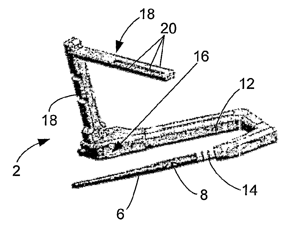
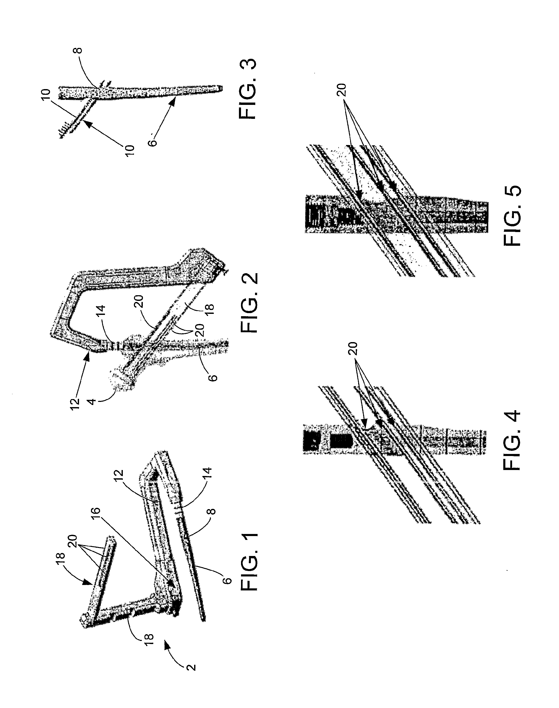
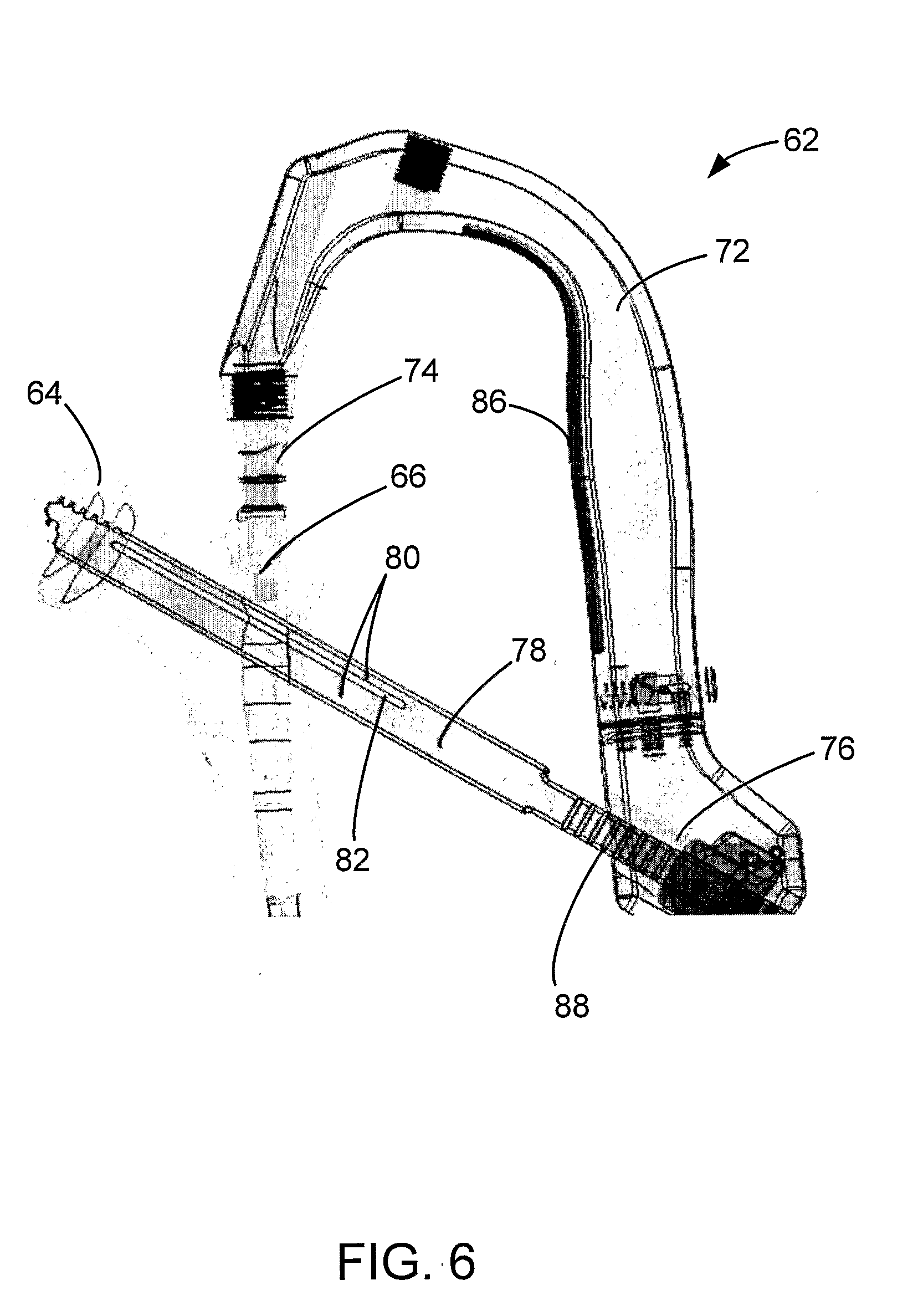
[0049]One embodiment of the present invention provides a drill guide for attaching to an implant inserted in contact with a bone (e.g., an intramedullary nail or bone plate inserted in contact with a humerus, femur, tibia, etc.) and a tower for use with the drill guide. The tower, or a portion of the tower, may be aligned with the holes in the implant under fluoroscopy or other x-ray technique. In certain embodiments, under fluoroscopy, the screw hole in the implant can be visualized because the implant material is less dense in the area of the holes. Once aligned, the tower device or a portion of the tower device may indicate the extents or boundaries of the securing member shaft or body. For example, the image of the tower device on a display of an imaging device may indicate or otherwise display the width of the screw. As another example, the tower device might extend or be adjusted to show, represent, or otherwise display the length of one or more different types of candidate se...


PUM


Abstract

PROBLEM TO BE SOLVED: To provide a perforating pin and equipment for perforation with which an accurate piercing region and piercing direction of a guiding pin can be easily specified at the neck of the femur or its surroundings and an advancing situation of the perforating pin can be confirmed when the perforating pin is pierced.
SOLUTION: The guide 1 for the perforating pin includes a main body section 2 which is equipped with a contacting section 8, a guiding channel 3 for the perforating pin and an operation section 9, a first advancing direction of the perforating pin displaying section 5 with which the advancing direction of the perforating pin 10 inserted in the guiding channel 3 can be confirmed by X-ray fluoroscopy, and a second advancing direction of the perforating pin displaying section 6 with which the advancing direction of the perforating pin 10 inserted in the guiding channel 3 can be confirmed by X-ray fluoroscopy from the different direction than the first advancing direction of the perforating pin displaying section 5. The bone perforating pin 10 can be confirmed by X-ray fluoroscopy with the first and the second advancing direction of the perforating pin displaying sections 5 and 6 while the perforating pin 10 inserted in the guiding channel 3 is superimposed on the displaying sections 5 and 6.

Description

RELATED APPLICATIONS[0001]The present application claims the benefit of provisional patent application Ser. No. 60 / 662,878 filed on Mar. 17, 2005 entitled “Screw Placement Device,” and provisional patent application Ser. No. 60 / 702,230 filed on Jul. 25, 2005 entitled “Screw Placement Device,” the contents of which are incorporated herein by these references.FIELD OF THE INVENTION[0002]The present invention relates generally to medical methods and systems. More specifically, the invention relates to methods and systems that utilize x-ray or fluoroscopic imaging technology and other devices to insert, place, or otherwise use intramedullary nails, bone plates and other implants as well as screws, pins, and other securing members.BACKGROUND[0003]Soon after the discovery of x-rays at the end of the 1800s, it was discovered that x-rays produce an image on photographic plates and penetrate many materials such as paper, wood, certain metals, and living tissue. The discovery provided, for th...

Claims


Application Information

Patent Timeline
Patent Type & Authority Applications(United States)
IPC IPC(8): A61B17/68
CPCA61B17/1703A61B17/1721A61B17/80A61B2017/00902A61B2017/00915A61B2019/5238A61B2090/376
Inventor FERRANTE, JOSEPH M.GRUSIN, N. KELLEYMINES, ANGELA B.RUSSELL, THOMAS ANTHONYSANDERS, ROYRAINS, JAMES K.GERLACH, DARIN
Owner SMITH & NEPHEW INC
Why Eureka
Try Eureka