Method and apparatus for precast wall and floor block system

a floor block and prefabricated technology, applied in the field of building systems, can solve the problems of limited stability, inefficient utilization of costly crane time, and limited stability of prior art systems, and achieve the effect of immediate stability

Inactive Publication Date: 2008-11-20
POWELL DAVID W
View PDF2 Cites 47 Cited by
  • Summary
  • Abstract
  • Description
  • Claims
  • Application Information

AI Technical Summary

Benefits of technology

[0009]The wall blocks may be designed for a particular application, or inventories may be maintained of standard wall lengths and features such as door and window locations. In one embodiment, a tongue and groove base key detail support

Problems solved by technology

These systems have the disadvantage of shoring requirements and limited stability until the cast-in-place joints have been placed and the concrete allowed time to gain strength.
These prio

Method used


Image

  • Method and apparatus for precast wall and floor block system
  • Method and apparatus for precast wall and floor block system
  • Method and apparatus for precast wall and floor block system

Examples


example

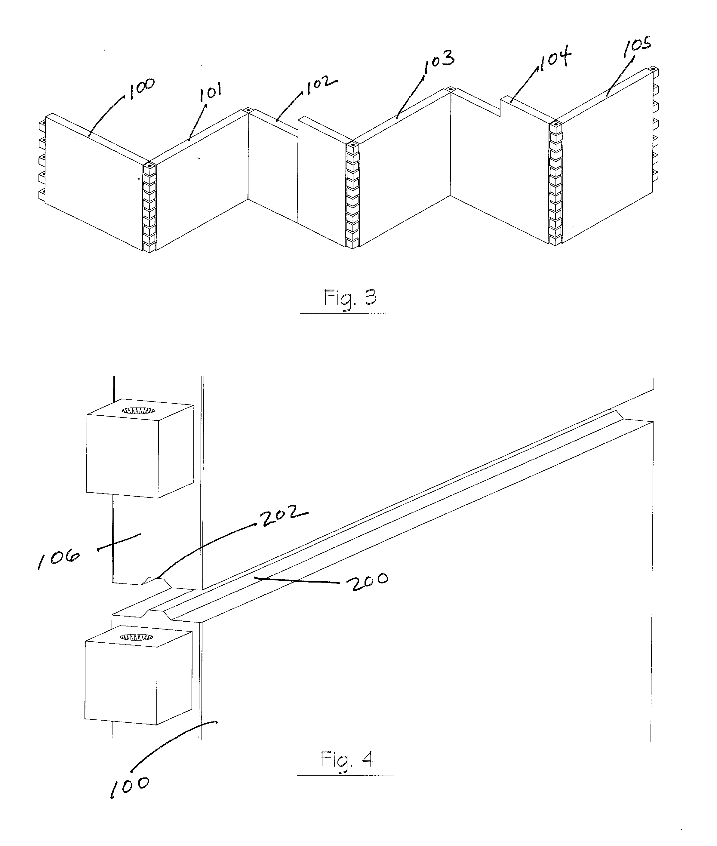
[0108]Where the offset of an architectural facade such as between blocks 630 and 631 of FIG. 38; or an interior wall such as blocks 632 and 633 is on the order of a single wall thickness, a variation of the finger joint can offer a solution. The pair of walls in FIG. 38 that point to the left each offer a finger pattern B for the forward wall, and also offer double pins and two double-width receivers to accommodate two fingers from a center wall that is inset by one wall thickness as shown in FIG. 39.

Finger Floor Block System

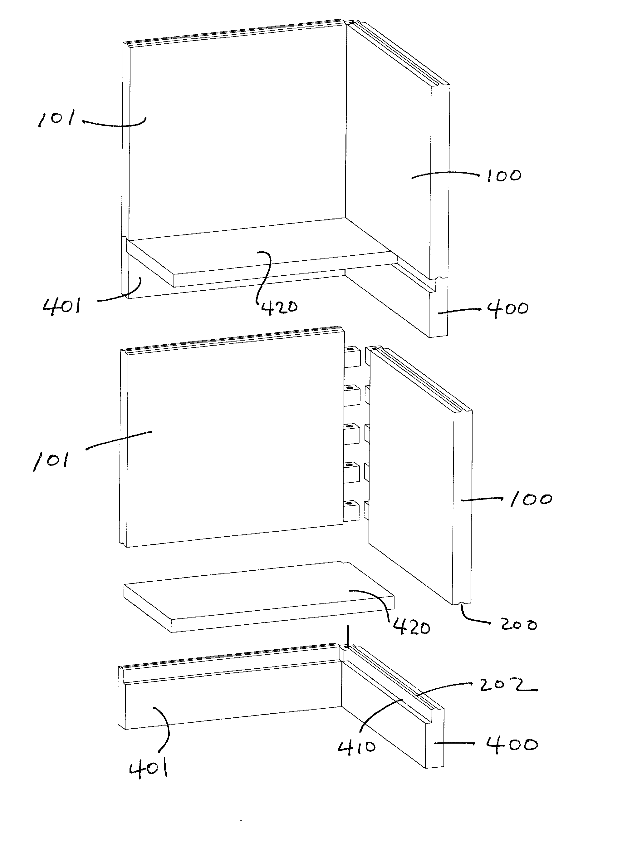
[0109]The ledge examples described in FIG. 11B above showed a 30 cm (12 in.) thick wall that could offer a 10 cm wide ledge 410 either side of a 10 cm keyed continuous plinth 200. This application also envisions a 20 cm (8 in.) or thinner wall that can carry floor on one or both sides and stack to build multi-story construction. The thinner walls feature full-width bearing ledges at interior bearings and half-width ledges at perimeter bearings, and they show a p...


PUM


Abstract

Precast planar construction wall blocks are provided with various configurations of fingers. Structures are rapidly assembled by aligning the fingers and inserting a pin through vertical sleeves provided in the fingers. Finger joints are typically shimmed and grouted for additional strength. Openings for doors and windows are provided in some wall blocks. Floor blocks are supported on ledges at the top of wall blocks or by portions of the top edges of wall blocks. A concrete or other topping may be added to floor blocks, and conduit may be run in the topping.

Description

[0001]This non-Provisional patent application is related to U.S. Provisional Application 60 / 930,229 which incorporated by reference Provisional Application 60 / 923,265. Application No. 60 / 930,229 was filed by applicant on May 15, 2007. This application claims the priority of the May 15, 2007 filing date.BACKGROUND OF THE INVENTION[0002]1. Field of the Invention[0003]This invention is related to a building system comprising precast structural building wall and floor blocks, the combination of those blocks to create structural elements, and methods of manufacturing, assembly, disassembly and reconfiguration of those blocks.[0004]2. Description of Related ArtLadderBlock™ Precision Precast Framing and Wall Systems[0005]LadderBlock™ precision precast framing and wall systems have been described in previous applications including copending U.S. patent applications Ser. Nos. 10 / 680939, 11 / 332696, and 11 / 745,998; and related PCT applications PCT / US03 / 31929, PCT / US / 06 / 01429, and PCT / US07 / 6849...

Claims


Application Information

Patent Timeline
IPC IPC(8): E04B1/343E04G21/14E04B2/00E04B5/00
CPCE04B1/04E04B5/023E04B5/04E04C2/04E04C2002/004
Inventor POWELL, DAVID W.
Owner POWELL DAVID W
Why Eureka
Try Eureka