
Flow guide element for guiding the flow of a fluid medium

a flow guide and fluid medium technology, applied in the direction of instruments, electrical control, combustion air/fuel air treatment, etc., can solve the problems of increasing separation and interference, difficult to achieve constructive adaptation, and the position of the guide blade must be adjusted very carefully, so as to reduce or avoid separation, increase the flow speed, and reinforce the effect of pulse exchang

Active Publication Date: 2008-11-20
ROBERT BOSCH GMBH
View PDF5 Cites 22 Cited by
  • Summary
  • Abstract
  • Description
  • Claims
  • Application Information

AI Technical Summary

Benefits of technology

The present invention provides a flow guide element that overcomes the shortcomings of previous flow guide elements. The flow guide element includes a flow tube with an elbow for diverting the flow, and at least one flow baffle with an opening. The opening has a specific shape and is positioned to prevent flow separations and enhance the pulse exchange between rapid and slow fluids. The flow baffle is designed to be relatively insensitive to its positioning and geometry, and may include a sheet metal baffle or other types of flow baffles. The openings have a round or multiangular shape, and may be positioned in a matrix or variable density. The invention provides an improved flow guide element for use in various fields such as internal combustion engines, natural science, and automobile construction.

Problems solved by technology

An important disadvantage of this design approach is that the geometry and the position of the guide blades has to be adapted very carefully to be effective.
Unfortunately, this constructive adaptation is not always possible, since the flow topology in air guidance systems frequently changes rapidly with flow speed.
In this case it may happen that the guide blades or sheet metal baffles themselves cause additional separations and interferences.

Method used


Image

  • Flow guide element for guiding the flow of a fluid medium
  • Flow guide element for guiding the flow of a fluid medium
  • Flow guide element for guiding the flow of a fluid medium

Examples


Embodiment Construction

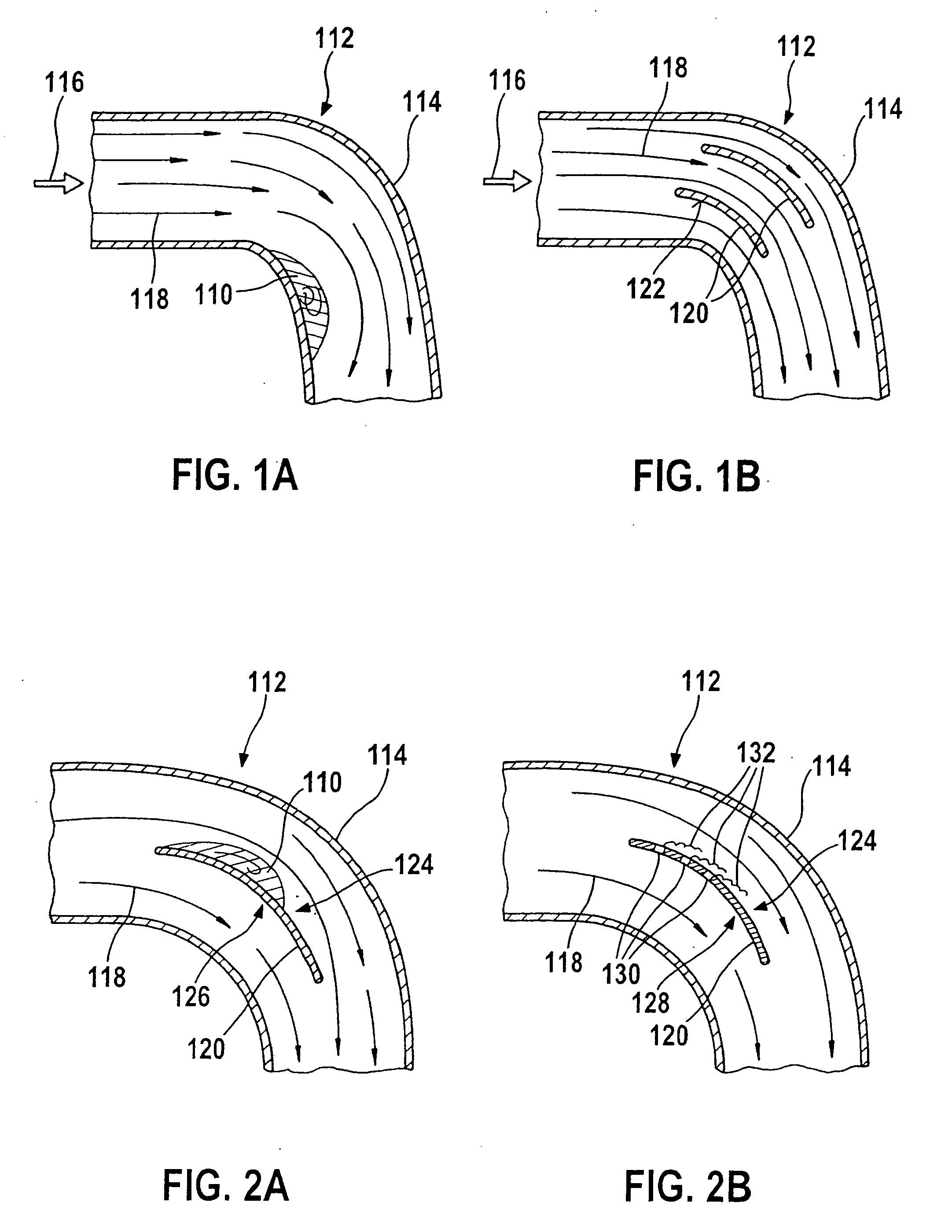
[0032]In FIGS. 1A and 1B, the known problem of the formation of separation regions 110 is shown in the region of elbows 112 of flow tubes 114. The fluid medium, in this instance, flows at a (local) main flow direction 116 through flow tube 114. Directly after being diverted in the region of elbow 112, there is formed a separation region 110, in the embodiment in FIG. 1A not having flow baffles, in which a very slow flow and a partial backflow prevail.

[0033]In this region, the flow, which is symbolically made clear in FIGS. 1A and 1B by flow lines 118, is compressed, and the flow cross section becomes narrower. The throughput of flowing fluid medium through flow tube 114 is reduced thereby. An additional problem is that separation regions 110 may be unstable laterally, whereby fluctuations in the throughput may occur.

[0034]FIG. 1B shows the arrangement shown in FIG. 1A, but in this case two flow sheet metal baffle 120 have been accommodated inside flow tube 114. These flow sheet meta...


PUM


Abstract

A flow guide element is provided for guiding a flow of a fluid medium which is particularly suitable for use in an intake tract of an internal combustion engine. The flow guide element includes a flow tube having an elbow for diverting the flow. In the region of the elbow there is situated, in this case, at least one flow baffle having at least one deflector. The deflector is penetrated by an opening, going right through the flow baffle, in at least one area.

Description

BACKGROUND INFORMATION[0001]The present invention relates to flow guide elements such as the ones used in various fields of natural science and technology. These flow guide elements are used as a part of flow guide systems which are used to guide flowing fluid media, especially gases or liquids over a specified path, for instance, to supply gases to a process or drain off exhaust gases from this process.[0002]One important field of application of a flow guide is motor vehicle technology, and within that field, especially the area of guiding gaseous media. A first important example in the field of motor vehicle technology is the area of air guidance in connection with air filters in the intake tract of internal combustion engines. The air taken in, in this instance, has to be guided from the air filter to the internal combustion engine by using several partially straight, partially curved pieces of tubing.[0003]A second example, in which flow guide elements are important, is air mass...

Claims


Application Information

Patent Timeline
Patent Type & Authority Applications(United States)
IPC IPC(8): F02M35/10
CPCF02D41/187F02M35/021F02M35/10013F02M35/10262F02M35/10386F15D1/04G01F1/6842G01F15/00Y02T10/146Y02T10/12
Inventor KONZELMANN, UWEGMELIN, CHRISTOPH
Owner ROBERT BOSCH GMBH
Learn More