Pneumatic tire
a technology of pneumatic tires and vulcanized rubber, which is applied in the field of pneumatic tires, can solve the problems of uneven adhesion between the windings, high electric resistance of vulcanized rubber, and high resistance of vulcanized rubber, and achieve the effects of reducing the thickness of each layer, improving the effect of wear resistance, and effective improvement of tread durability
Inactive Publication Date: 2008-11-20
SUMITOMO RUBBER IND LTD
View PDF9 Cites 22 Cited by
- Summary
- Abstract
- Description
- Claims
- Application Information
AI Technical Summary
Benefits of technology
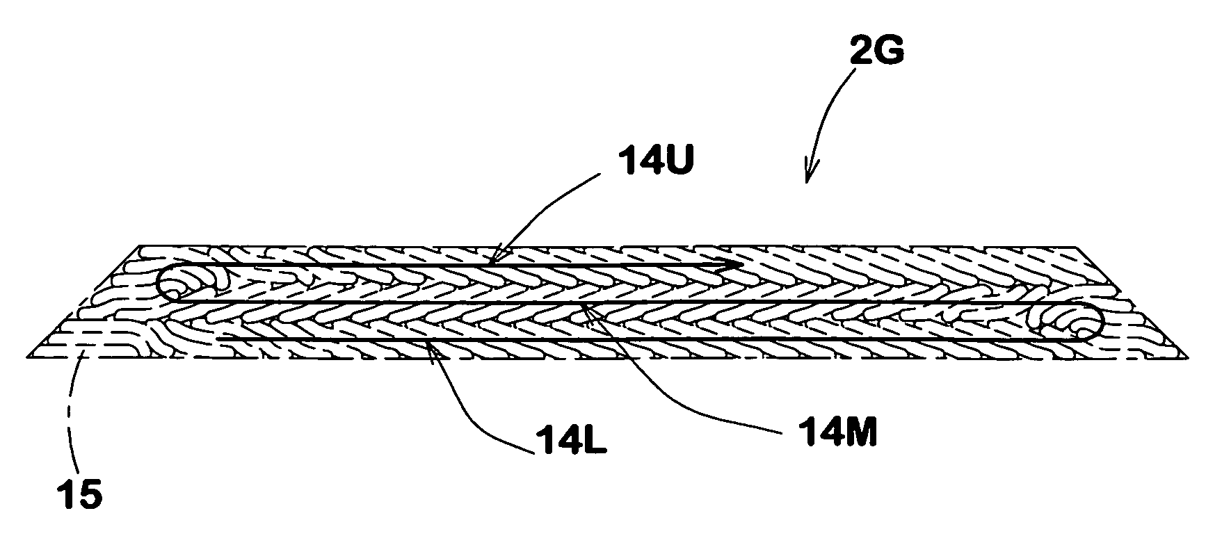
[0019]Therefore, as the thickness of the tread rubber is divided into a plurality of layers, the thickness of each layer decreases. As a result, the windings of the tape are largely leaned each against the adjacent one. Accordingly, in the process of making the green tire, it becomes easy to press the overlapped windings of the tape each other during winding the tape into the tread rubber, because the largely inclined windings can be pressed each other by applying a force in the tire radial direction, for example, using a pressure roller. Further, in the process of vulcanizing the green tire pu
Problems solved by technology
In the case of the silica-rich rubber compounds, however, the electric resistance of the vulcanized rubber becomes very high, and almost insulative.
Accordingly, it is difficult to press the windings each other to make close contact.
Therefore, there is a possibility that the adhesion between the windings becomes uneven though their joint surfaces are liable to be subjected
Method used
View moreImage
Smart ImageViewing Examples

Examples
 PUM
 Abstract
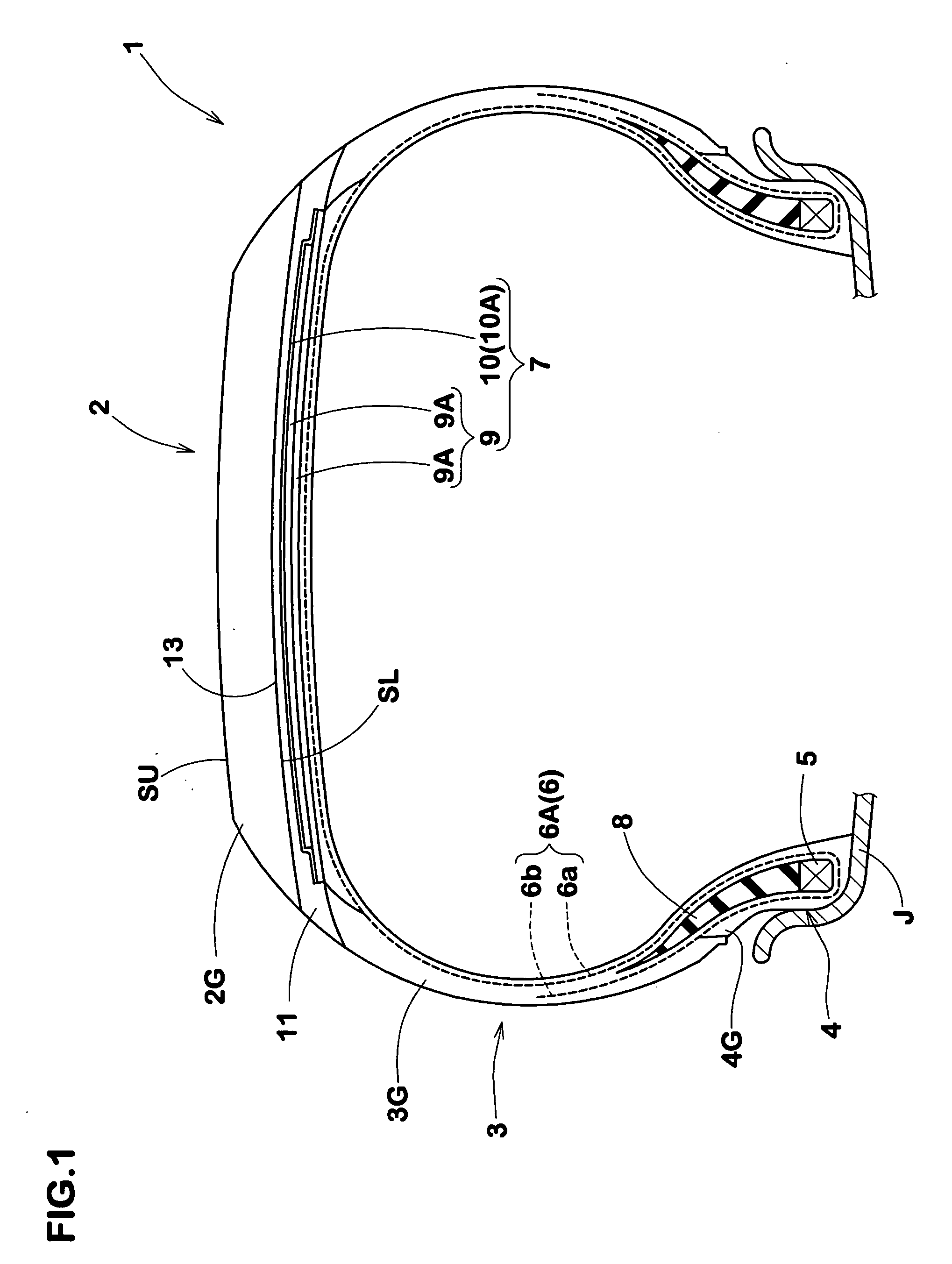
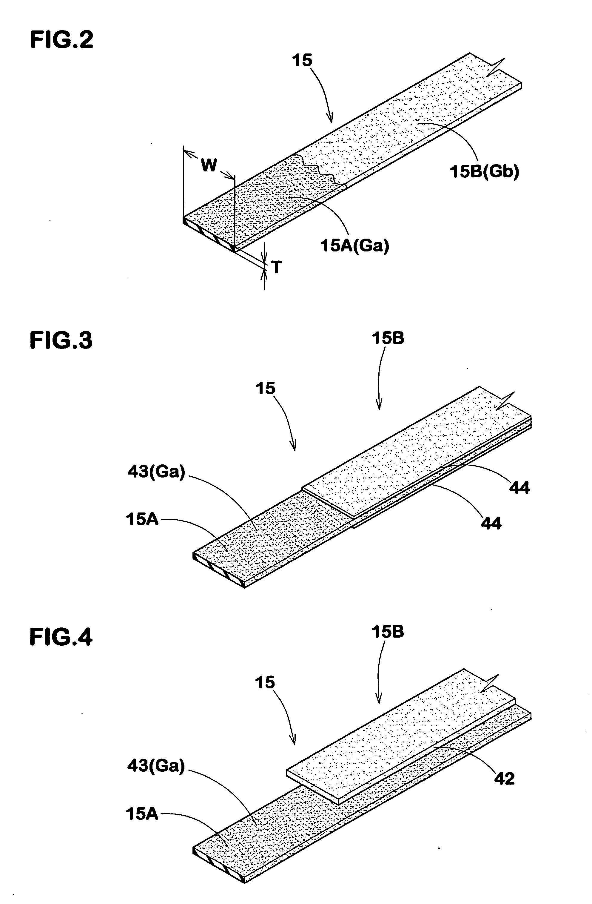
A pneumatic tire comprises a tread rubber comprising layers each formed by overlap winding a rubber tape. The rubber tape in each layer has a conductive part in the longitudinal direction of the tape and the remaining less-conductive part, wherein the conductive part is wound at least once around the tire. In the radially outermost layer, the conductive part is exposed in the tread surface by a total axial width WU of at least 1.0 mm. In the radially innermost layer, the conductive part appears in the radially inner surface so as to be electronically connected to a conductive underlying structure by a total axial width WL of at least 1.0 mm. Between the radially adjacent layers, the conductive part in the radially outer layer is connected to the conductive part in the radially inner layer by a total axial width WM of at least 1.0 mm. Preferably, the rubber tape is made of mainly a silica rich compound.
Description
BACKGROUND OF THE INVENTION [0001]The present invention relates to a pneumatic tire, more particularly to a structure of the tread rubber composed of multiple windings of a rubber tape mainly made of a less-conductive rubber compound such as silica rich compound.[0002]In recent years, there is a pressing need to reduce oil consumption by automobiles. Accordingly, it is a very important theme for tire manufactures to improve the rolling resistance of a pneumatic tire.[0003]In order to improve the rolling resistance, the use of a silica-rich rubber compound as the tread rubber has been proposed. In the case of the silica-rich rubber compounds, however, the electric resistance of the vulcanized rubber becomes very high, and almost insulative. Therefore, in order to discharge static electricity to the ground through the tread portion, it is necessary to form a discharging path penetrating through the tread rubber.[0004]On the other hand, in order to reduce the tire plant size and save t...
Claims
Login to View More Application Information
Patent Timeline
 IPC IPC(8): B60C19/08
CPCB29D30/3028B29D30/60B29D2030/526B60C19/08
Inventor MAFUNE, TOSHIYUKINOBUCHIKA, HIDEO
Owner SUMITOMO RUBBER IND LTD
Features
- Generate Ideas
- Intellectual Property
- Life Sciences
- Materials
- Tech Scout
- Unparalleled Data Quality
- Higher Quality Content
- 60% Fewer Hallucinations
Learn More Browse by: Latest US Patents, China's latest patents, Technical Efficacy Thesaurus, Application Domain, Technology Topic, Popular Technical Reports.
© 2025 PatSnap. All rights reserved.Legal|Privacy policy|Modern Slavery Act Transparency Statement|Sitemap|About US| Contact US: help@patsnap.com