
Cooling device

a cooling device and cooling technology, applied in lighting and heating apparatus, ventilation systems, heating types, etc., can solve the problems of deteriorating the efficiency and lifespan of cooling fans, affecting the operation stability of cooling fans, and consuming partial electrical energy, so as to improve the heat dissipation area and heat dissipation performance of the circuit board, and facilitate fast heat dissipation. , good cooling mechanism

Inactive Publication Date: 2008-11-20
SUNONWEALTH ELECTRIC MACHINE IND
View PDF2 Cites 17 Cited by
  • Summary
  • Abstract
  • Description
  • Claims
  • Application Information

AI Technical Summary

Benefits of technology

[0010]In view of the foregoing concern, the present invention thus provides a cooling structure for motor of fan, whose main object targets at achieving the function of lowering the temperature rise of a heat-generating electronic component under the premise of no change of the original mechanism design. The cooling structure has a highly heat-conductive metal integrated with at least one side of a circuit board to enhance the heat dissipation area and heat transfer performance of the circuit board, and at least one part of the circuit board is protruded beyond a hub of an impeller so as to position the protrusion at a downwind place of blades of the impeller to facilitate fast heat dissipation. Consequently, the present invention can carry out heat dissipation of the entire circuit board and the heat-generating electronic component by the heat transfer function of the highly heat-conductive metal to similarly attain a good cooling mechanism without altering the original mechanism design.
[0011]A second object of the present invention is to prevent the heat-generating electronic component from being interfered by electrostatic charge in the air flow field. The present invention can carry out heat dissipation of the entire circuit board and the heat-generating electronic component such that the heat-generating electronic component on the circuit won't be necessarily exposed in the air flow field so as to ensure that its normal operation function won't be interfered due to electrostatic interference.

Problems solved by technology

As a result, while the heat-generating electronic component is operated, its material certainly consumes partial electrical energy and converts that into thermal energy.
Accordingly, the heat-generating electronic component 32 lacks of an adequate cooling mechanism, easily impacts on its operational stability due to an excessively high temperature and even deteriorates the efficacy and lifespan of the cooling fan.
However, such solution also gives rise to the issues of the conflict between the blades 23 and the heat-generating electronic component 32 accruing electrostatic interference at the same time.

Method used


Image

  • Cooling device
  • Cooling device
  • Cooling device

Examples


Embodiment Construction

[0021]To make the object, characteristic and performance of the present invention more self-explanatory, two preferred embodiments of the present invention are provided as follows together with the illustration of the figures.

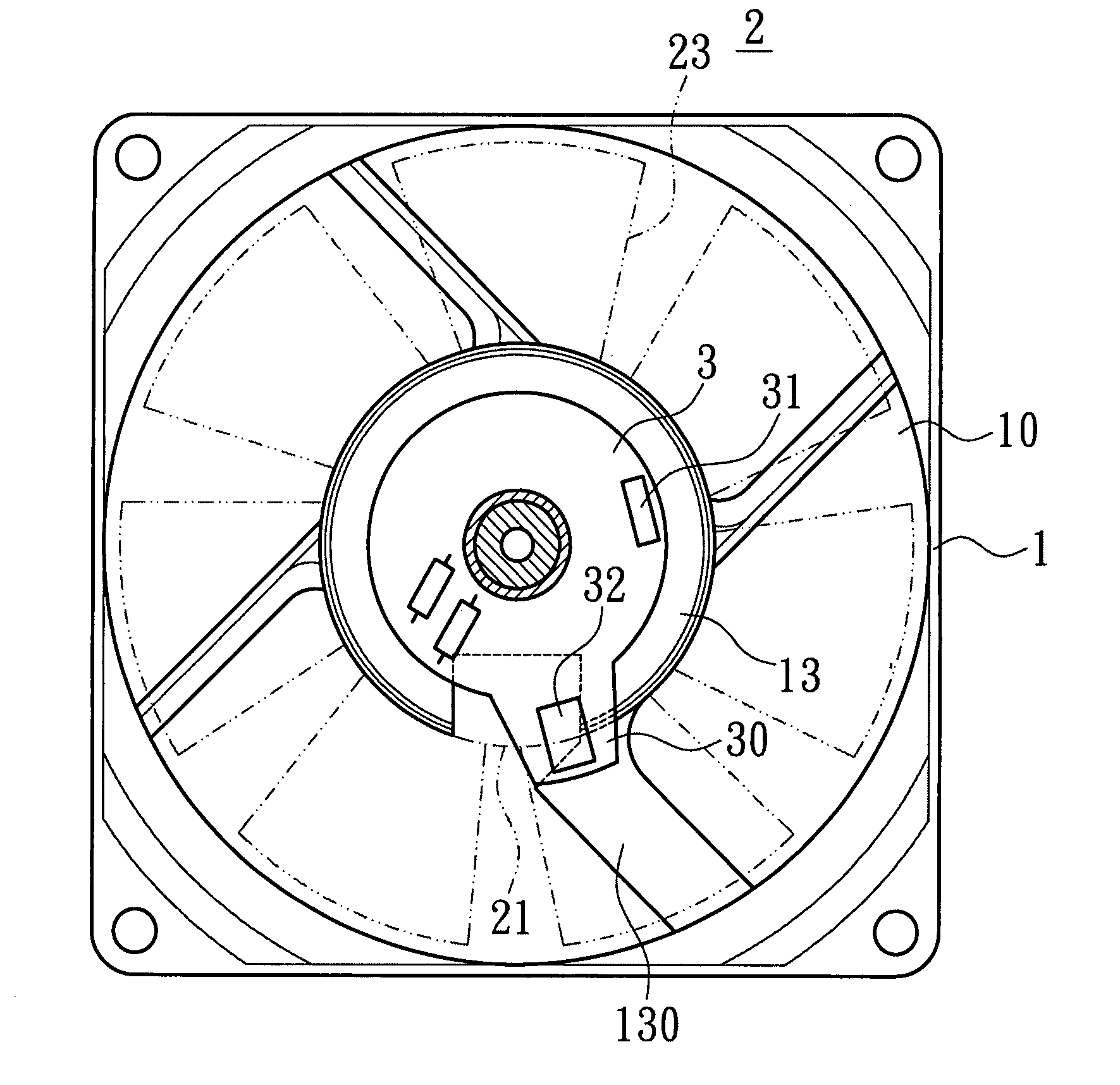
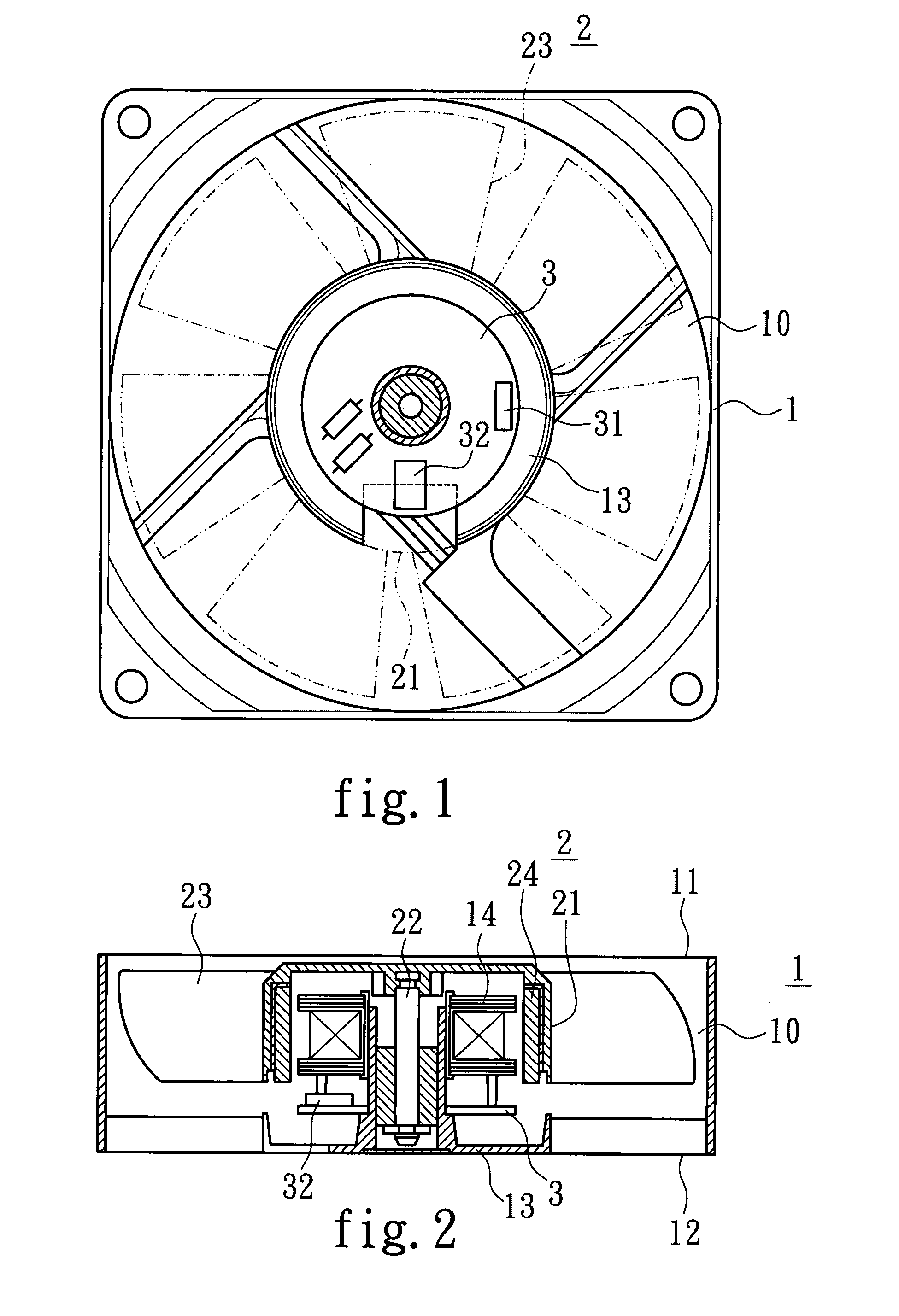
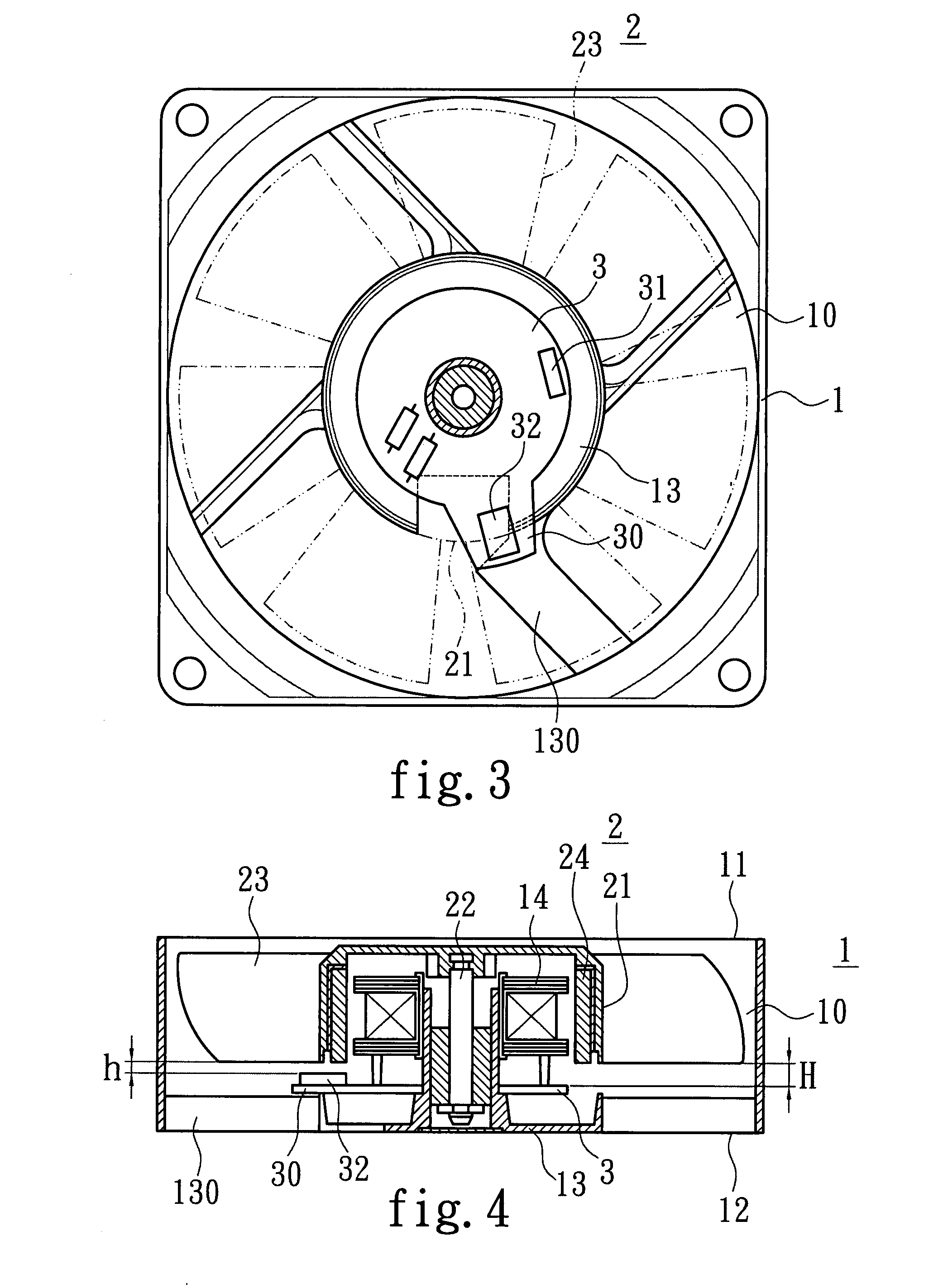
[0022]As shown in FIG. 5, a first preferred embodiment of the present invention includes a housing 1, an impeller 2 and a circuit board 3.

[0023]Together with the reference to FIG. 6 and FIG. 7, the housing has an air flow channel 10, an air inlet 11, an air outlet 12, a base 13 and a stator set 14. The air flow channel 10 can accommodate an impeller 2, the air inlet 11 and the air outlet are located on both sides of the air flow channel 10 such that air flow is inputted to the air inlet 11 and outputted from the air outlet 12, the base 13 is selectively disposed beside the air outlet 12 or the air inlet 11 depending on the requirement of actual heat-dissipation occasion and has a plurality of ribs 130, a shaft tube 131 and at least a cable gap 133, in which eac...


PUM


Abstract

The present invention relates to a cooling structure for motor of fan, which includes a housing, an impeller and a circuit board. The housing has an air flow channel and a base; the base is located on one side of the air flow channel to support the circuit board, and the impeller is movably integrated on the base; the circuit board is bonded with a highly heat-conductive metal on at least one side thereof so as to provide good heat dissipation and heat transfer performance; at least one portion of the circuit board is extended beyond the hub of the impeller such that the extended portion is located at a downwind place of the blades of the impeller to facilitate fast heat dissipation.

Description

FIELD OF THE INVENTION[0001]The present invention relates to a cooling structure for motor of fan, and more particularly to a cooling fan that achieves the object of temperature rise for its heat-generating electronic components without changing the original mechanism design, to prolong the operation lifespan of fan.BACKGROUND OF THE INVENTION[0002]As shown in FIG. 1 and FIG. 2, a conventional cooling fan structure includes a housing 1, an impeller 2 and a circuit board 3.[0003]The housing 1 has an air flow channel 10, an air inlet, an air outlet, a base 13 and a stator set 14, in which the air flow channel 10 accommodates the impeller 2 such that air flow is inputted from the air inlet 11 and outputted from the air outlet 12, the base is located beside the air inlet 12 for carrying the circuit board 3, and the stator set 14 and is integrated with the impeller 2.[0004]The impeller 2 has a hub 21, a spindle 22, several bladed and an annular magnet 24, in which the spindle 22 is locat...

Claims


Application Information

Patent Timeline
Patent Type & Authority Applications(United States)
IPC IPC(8): F24F7/007
CPCF04D25/068F04D29/584F04D25/0633F04D29/5813
Inventor HORNG, ALEXHSU, SHIH-CHANGLO, PEN-WEN
Owner SUNONWEALTH ELECTRIC MACHINE IND
Features
  • Generate Ideas
  • Intellectual Property
  • Life Sciences
  • Materials
  • Tech Scout
  • Unparalleled Data Quality
  • Higher Quality Content
  • 60% Fewer Hallucinations
Learn More