Autofocus Device and Microscope Using the Same

a technology of automatic focusing and microscope, which is applied in the direction of instruments, optical elements, television systems, etc., can solve the problems of out-of-focus owing to a tilt of the optical system, and the shape of the sample itself becomes a problem, and achieve the effect of accurate determination of in-focus position and short tim

Inactive Publication Date: 2008-11-20
HAMAMATSU PHOTONICS KK
View PDF6 Cites 29 Cited by
  • Summary
  • Abstract
  • Description
  • Claims
  • Application Information

AI Technical Summary

Benefits of technology

[0010]According to the automatic focusing device and the microscope apparatus using the same of the present invention, with regard to the focal point measurement for determining an in-focus position, by acquiring a plurality of images of a sample while continuously changing the focal position, carrying out two times of focal point measurement in different focal position changing directions, and determining an in-focus position with reference to focal point measurement values calculated in each thereof, it becomes possible to accurately determine an in-focus position for an observation position of the sample in a short time.

Problems solved by technology

When an image of a sample is acquired by use of a microscope, out-of-focus owing to a tilt of the optical system or mechanical system in an apparatus or a tilt or an uneven shape of the sample itself becomes a problem.

Method used


Image

  • Autofocus Device and Microscope Using the Same
  • Autofocus Device and Microscope Using the Same
  • Autofocus Device and Microscope Using the Same

Examples


Embodiment Construction

[0020]Hereinafter, preferred embodiments of an automatic focusing device and a microscope apparatus using the same according to the present invention will be described in detail with reference to the accompanying drawings. Here, in the description of the drawings, identical elements are designated with identical numerical symbols so as to avoid overlapping descriptions. Dimensional ratios of the drawings are not always coincident with those in the description.

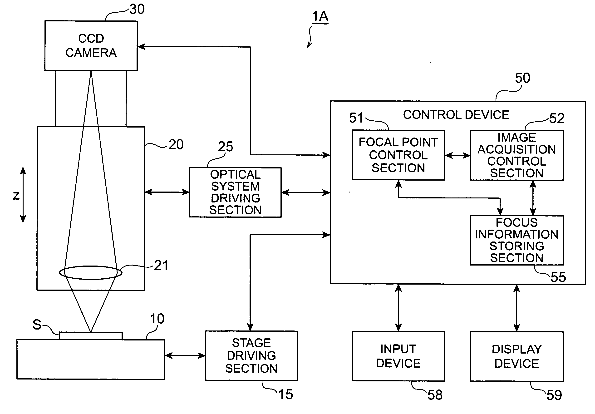
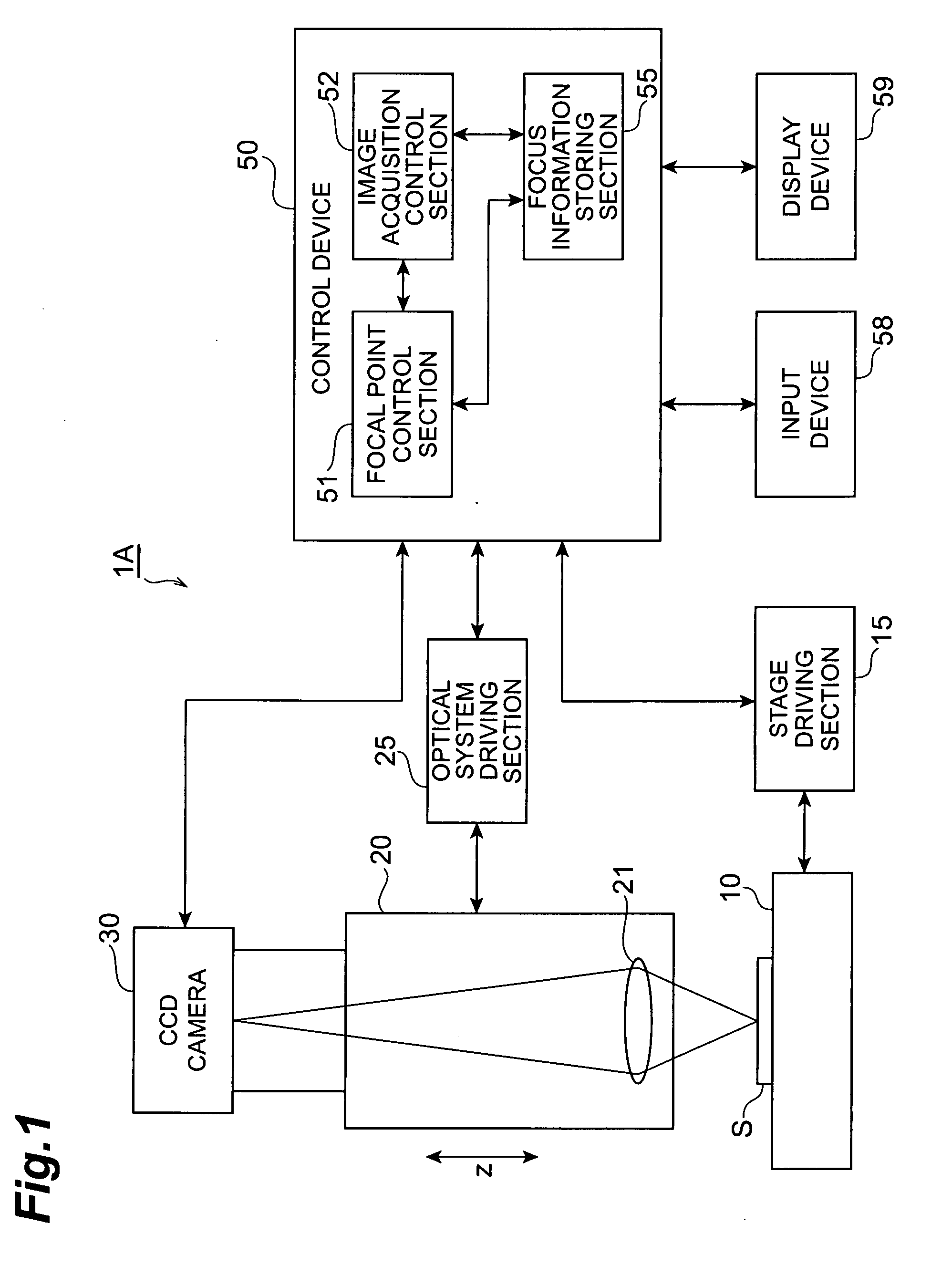
[0021]FIG. 1 is a block diagram showing a configuration of an embodiment of a microscope apparatus using an automatic focusing device according to the present invention. This microscope apparatus 1A is used for acquiring an image of a sample S. Here, the vertical direction to be an optical axis direction in the microscope apparatus 1A is provided as a z-axis direction, and the horizontal direction being a direction perpendicular to the optical axis is set as an x-axis direction and a y-axis direction. In addition, the sample S ...


PUM


Abstract

A microscope apparatus 1A is formed with a CCD camera 30 that acquires an image of a sample S, a light guiding optical system 20 that guides an optical image of the sample S to the camera 30, an optical system driving section 25 that drives the camera 30 and the optical system 20 to change a focal position on the sample S in a z-axis direction, and a control device 50 that includes a focal point control section 51. The focal point control section 51 calculates a first focal point measurement value from a plurality of images acquired by a first focal point measurement that is executed while continuously changing the focal position in one direction, calculates a second focal point measurement value from a plurality of images acquired by a second focal point measurement that is executed while continuously changing the focal position in a direction opposite that of the first focal point measurement, and determines an in-focus position for the sample S based on the first and second focal point measurement values. This realizes an automatic focusing device that is capable of accurately determining an in-focus position in a short time and a microscope apparatus using the same.

Description

TECHNICAL FIELD[0001]The present invention relates to an automatic focusing device for controlling a focal point when acquiring an image of a sample and a microscope apparatus using the automatic focusing device.BACKGROUND ART[0002]When an image of a sample is acquired by use of a microscope, out-of-focus owing to a tilt of the optical system or mechanical system in an apparatus or a tilt or an uneven shape of the sample itself becomes a problem. To cope therewith, conventionally, automatic focusing (autofocus) has been carried out in a microscope apparatus for automatically controlling a focal point of imaging by an image pickup device such as a CCD camera. A device that carries out such automatic focusing includes, for example, a device described in Patent Document 1.Patent Document 1: Japanese Patent Application Laid-Open No. H05-288981DISCLOSURE OF THE INVENTIONProblems to be Solved by the Invention[0003]In the above-described Document 1, disclosed is a method for acquiring a sa...

Claims


Application Information

Patent Timeline
Patent Type & Authority Applications(United States)
IPC IPC(8): G02B27/64G02B21/00
CPCG02B7/38G02B21/367H04N5/23212H04N23/67
Inventor UCHIYAMA, SHIGERUINOUE, TAKAYUKIOKUGAWA, MASATOSHI
Owner HAMAMATSU PHOTONICS KK
Why Eureka
Try Eureka