Noise detection circuit

a noise detection and circuit technology, applied in the direction of noise figure or signal-to-noise ratio measurement, instruments, semiconductor devices, etc., can solve the problem of not being able to accurately measure noise occurring in the circuit inside the chip, the referential voltage created through a low-pass filter b>101/b> will fluctuate, and the path for detecting noise of the ground line cannot be accurately measured. to achieve the effect of accurately comprehending and extracting nois

Inactive Publication Date: 2008-11-20
RENESAS ELECTRONICS CORP
View PDF5 Cites 24 Cited by
  • Summary
  • Abstract
  • Description
  • Claims
  • Application Information

AI Technical Summary

Benefits of technology

[0031]According to the present invention, not only noise detection of the first power supply line, but also noise detection of the second power supply line is possible, and it is possible to more accurately comprehend (i.e...

Problems solved by technology

However, in a circuit of Patent Document 1, a path for measuring power supply noise from a power supply line through a high-pass filter 103 is provided, but there is no path for detecting noise of a ground line.
In cases in which ground noise is present, there is a risk that a referential voltage created through a low-pass filter 101 will fluct...

Method used


Image

  • Noise detection circuit
  • Noise detection circuit
  • Noise detection circuit

Examples


example 1

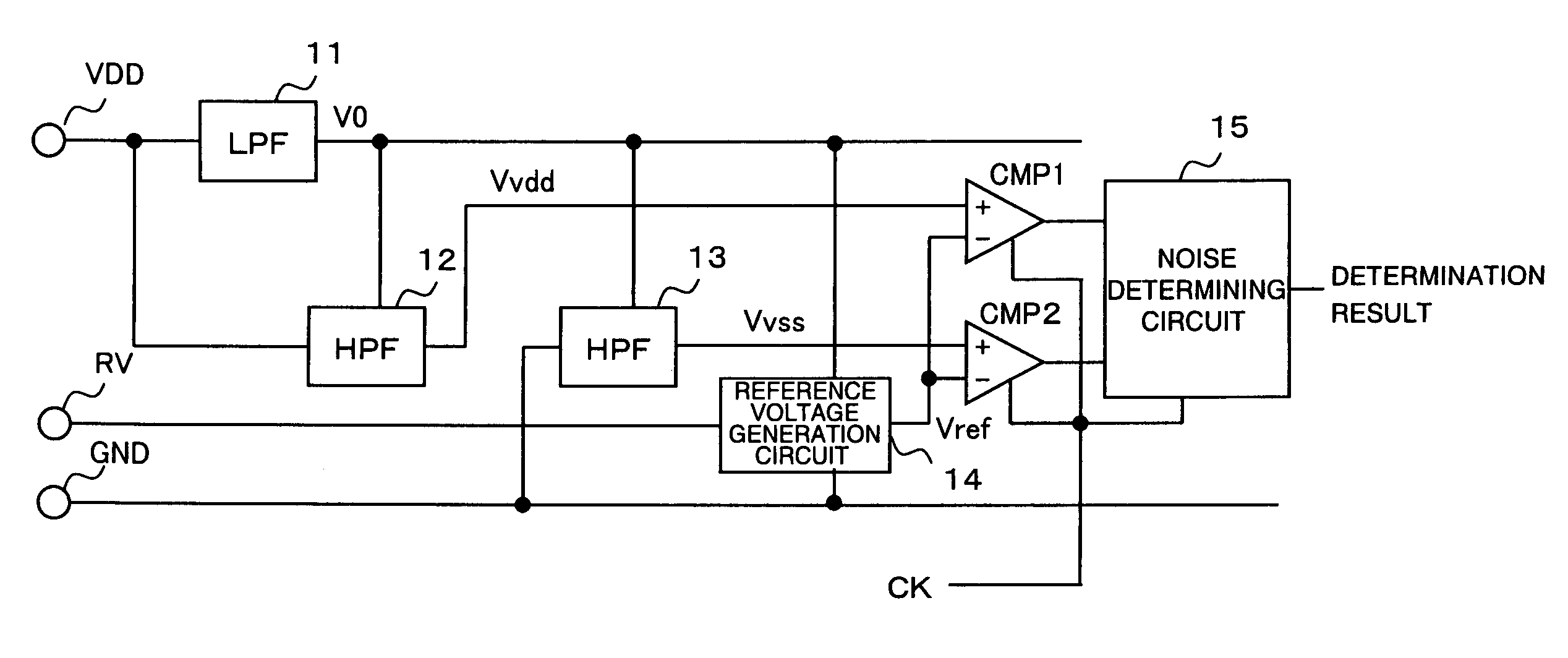
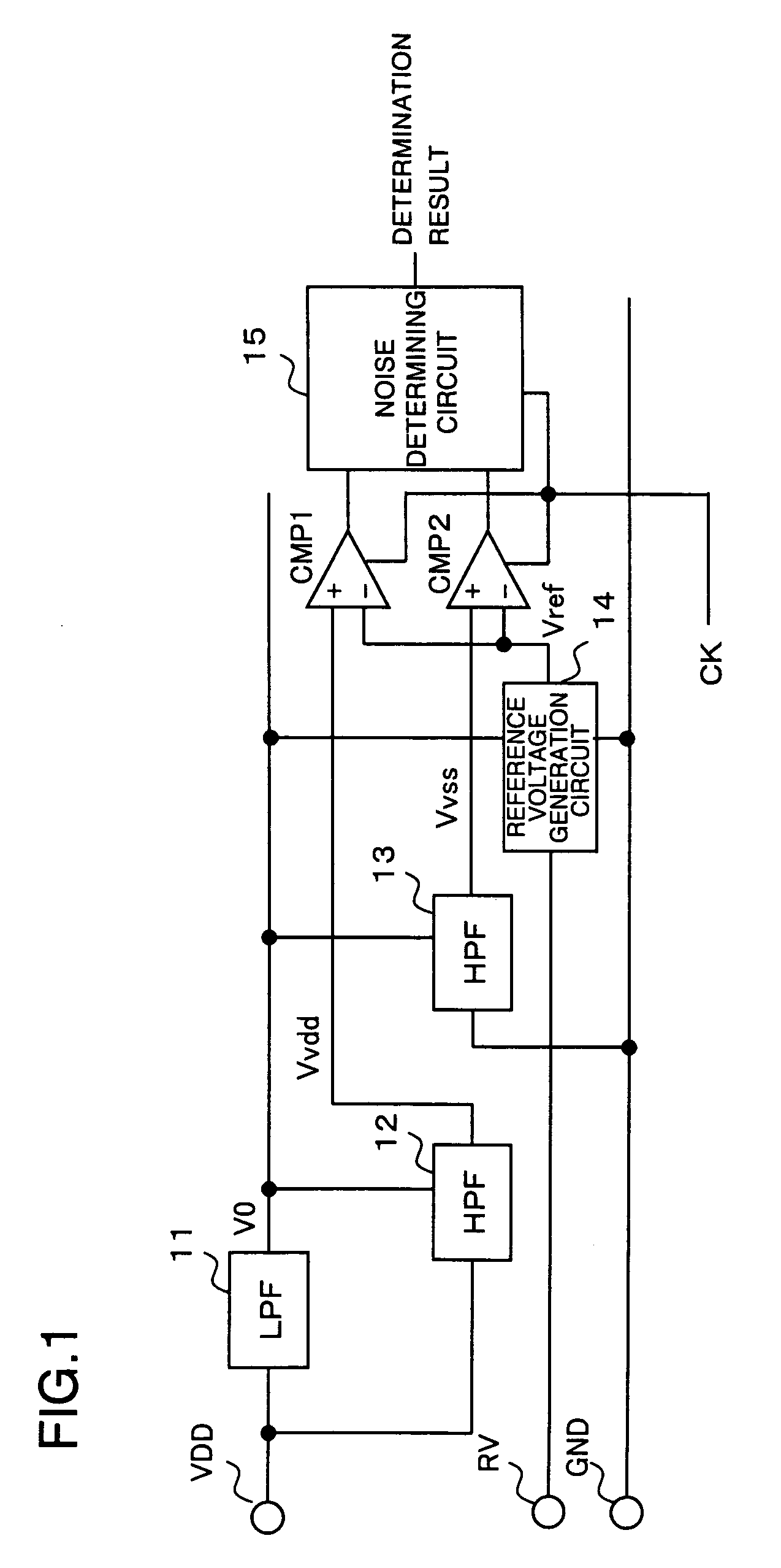
[0055]Next, an explanation is given concerning a specific circuit example of the noise detection circuit. FIG. 3 is a circuit diagram of main parts of the noise detection circuit according to the exemplary embodiment of the present invention.

[0056]A low-pass filter 11 is composed of a resistance element Rlpf and a capacitive element Clpf. A cutoff frequency of the low-pass filter 11 is set lower than a frequency in which noise is included, and values of the resistance element Rlpf and the capacitive element Clpf are decided so that a noise component is sufficiently removed. Furthermore, ground to which the capacitive element Clpf is connected is preferably static ground without noise. Therefore, a terminal on a side not connected to the low-pass filter output terminal side of the capacitive element Clpf is preferably connected to ground Gex, such as a board or the like, close to static ground. Here, in cases in which the noise detection circuit is embedded in the semiconductor devic...


PUM


Abstract

Noise occurring in a circuit is more accurately detected. A low-pass filter (11) is connected to a power supply line for a power supply terminal (VDD), and noise in the power supply line is removed to generate and output a referential voltage (V0). A high-pass filter (12) is connected to a power supply line, and a noise signal in the power supply line is passed with the referential voltage (V0) as a reference. A high-pass filter (13) is connected to a ground line for a ground terminal (GND), and a noise signal in the ground line is passed based on the referential voltage (V0) as a reference. A reference voltage generation circuit (14) generates and outputs a reference voltage (Vref) based on the referential voltage (V0) as a reference. Comparison circuits (CMP1 and CMP2) respectively compare output voltage of the high-pass filters (12 and 13) and the reference voltage (Vref). A noise determining circuit (15) changes the reference voltage (Vref) to obtain a comparison result at the same time for the comparison circuits (CMP1 and CMP2).

Description

REFERENCE TO RELATED APPLICATION[0001]This application is based upon and claims the benefit of the priority of Japanese patent application No. 2007-128041, filed on May 14, 2007, the disclosure of which is incorporated herein in its entirety by reference thereto.FIELD OF THE INVENTION[0002]This invention relates to a noise detection circuit, and in particular to a noise detection circuit for detecting noise generated in a power supply inside a semiconductor chip.BACKGROUND OF THE INVENTION[0003]In recent years, power supply noise environment in LSI chips has deteriorated due to increasing speeds, increased precision, and increased density of LSI chips, and trouble due to the power supply noise has been increasing. As a result, measurement of power supply noise actually generated inside an LSI chip is becoming important. A power supply noise measurement device that measures this type of power supply noise is described for example in Patent Document 1.[0004]FIG. 6 is a block diagram s...

Claims


Application Information

Patent Timeline
IPC IPC(8): H01L29/00
CPCG01R29/26G01R31/31721
Inventor SOUDA, MASAAKI
Owner RENESAS ELECTRONICS CORP
Why Eureka
Try Eureka