Projection Device with a Folded Optical Path and Wire-Grid Polarizer

a projection device and optical path technology, applied in the field of rear-projection display system, can solve the problems of degrading the performance of thin film material in applications, increasing the depth and overall footprint of the rear-projection system, and limited folding optical path length, so as to achieve the effect of increasing contrast and ensuring optical performance and structure properties

Inactive Publication Date: 2008-11-20
MOXTEK INC
View PDF99 Cites 3 Cited by
  • Summary
  • Abstract
  • Description
  • Claims
  • Application Information

AI Technical Summary

Benefits of technology

[0007]It has been recognized that it would be advantageous to develop a wire grid polarizer or polarizer device capable of being used in a rear-projection system with an overall box depth of less than 7 inches. In addition, it has been recognized that it would be advantageous to develop a wire grid polarizer with certain optical performance and structure properties to increase contrast in a rear-projection system. In addition, it has been recognized that it would be advantageous to develop a wire grid polarizer with anti-reflective properties to enable the control of the ambient room light reflecting from the front screen of a rear-projection system.

Problems solved by technology

This method is undesirable because it increases the depth and overall footprint of the rear-projection system.
The performance of the thin film material is degraded in the application as wide angles of incidence are needed to access larger dimensions.
Thus, the folded optical path length is limited, and the thinness of the overall system is limited, by the limitations of the thin film material at larger angles of incidence.

Method used


Image

  • Projection Device with a Folded Optical Path and Wire-Grid Polarizer
  • Projection Device with a Folded Optical Path and Wire-Grid Polarizer
  • Projection Device with a Folded Optical Path and Wire-Grid Polarizer

Examples


Embodiment Construction

)

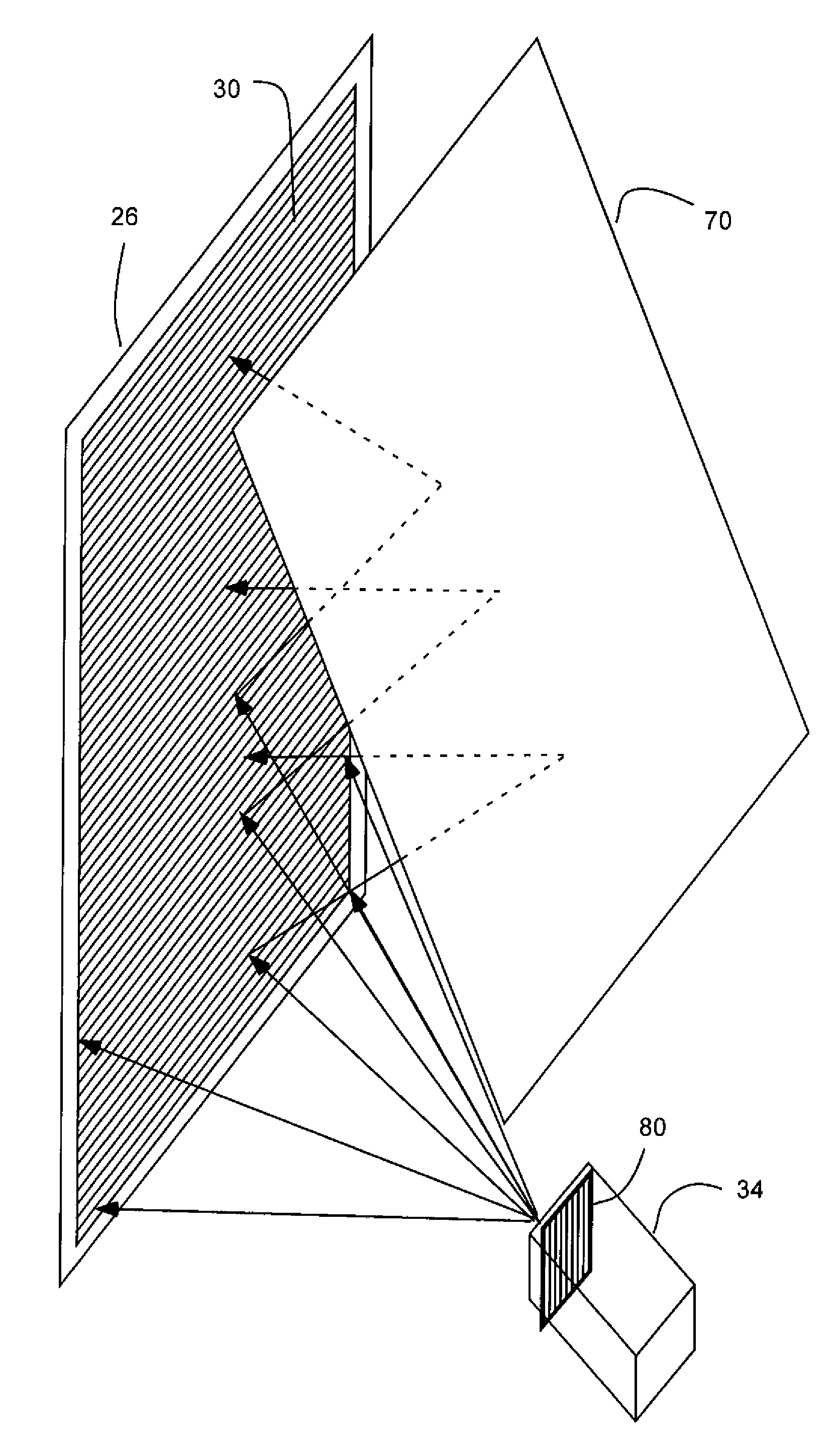
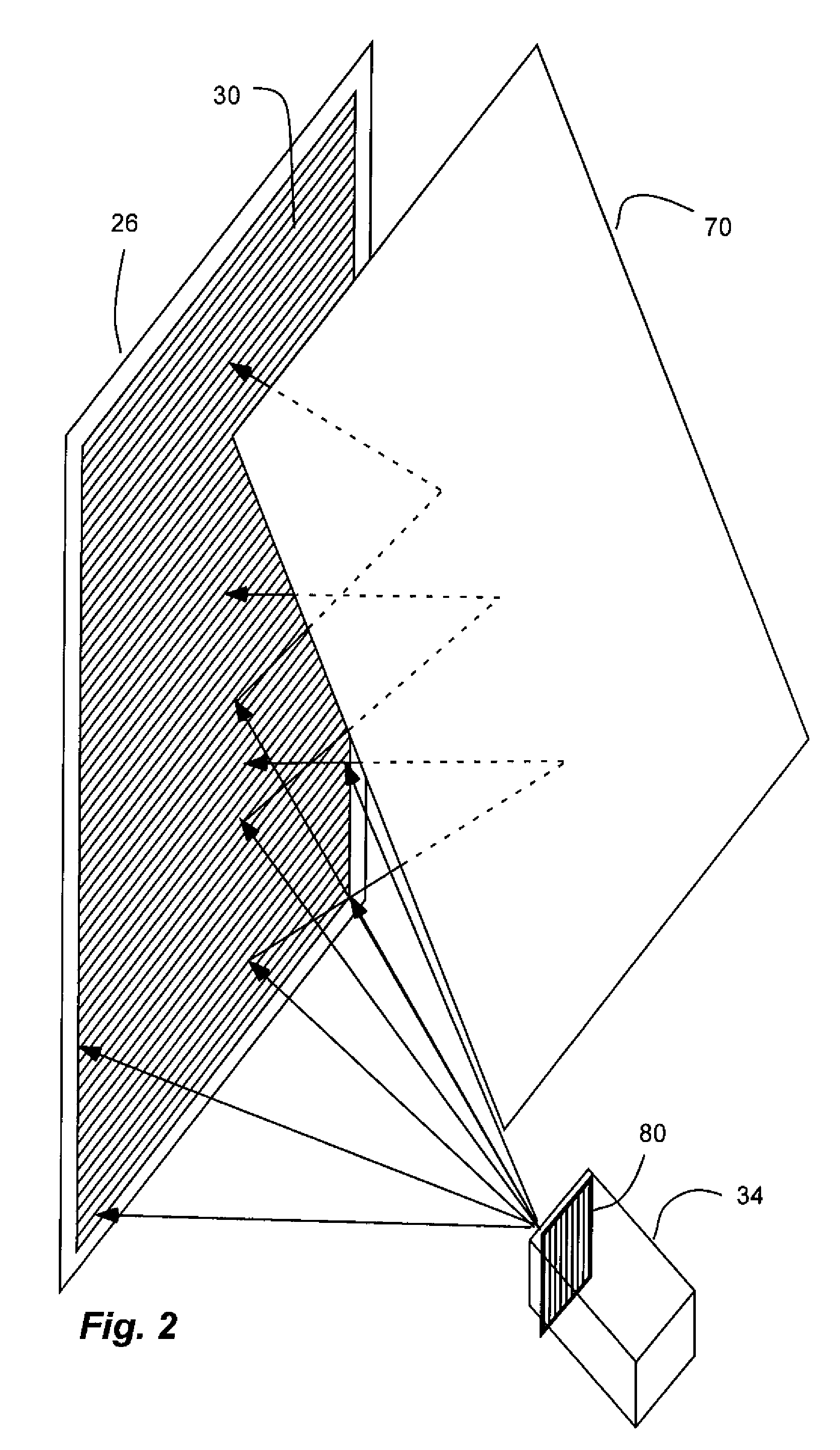
[0027]It has been recognized that a wire-grid polarizer can be utilized and optimized in a folded rear-projection system. Such a polarizer can have a steep acceptance angle. Wire-grid polarizers operate on principles related to the properties of the materials in the wire-grid, and on principles based on form birefringence, or the geometric structure of the wire-grid. It is therefore possible to create a wire-grid polarizer with the necessary performance to meet the requirements of a small-footprint, large-screen rear-projection system which cannot be met by thin-film materials with multiple, continuous thin film layers.

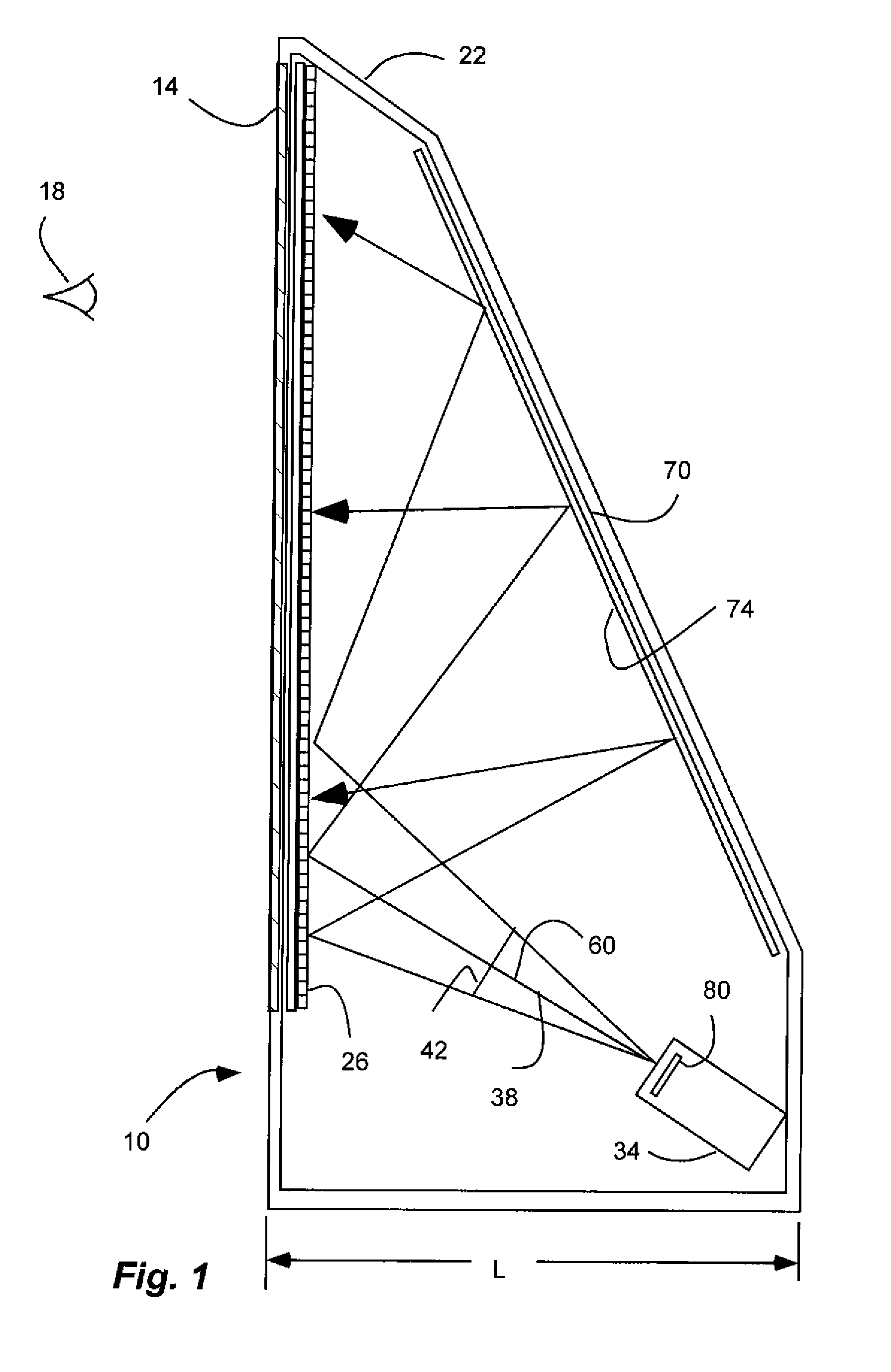
[0028]As illustrated in FIGS. 1-3c and 3e, a projection display system, indicated generally at 10, in an example implementation in accordance with the invention is shown. The system 10 is configured as a rear projection television. Such a system can be configured to receive and process an image signal, as is known in the art. The system 10 includes a screen 14 with a...


PUM


Abstract

A folded projection display system includes a wire-grid polarizer placed immediately behind the system's imaging screen. The display system includes an image projector that projects an image beam containing light of a predetermined linear polarization toward the imaging screen. The wire-grid polarizer reflects the light in the image beam away from the screen. The reflected image beam then encounters a ¼-wavelength achromatic retarder that converts the linear polarization to circular polarization. The image beam next hits a mirror that reflects the light back through the ¼-wavelength achromatic retarder, which converts the circular polarization back to linear polarization, with the polarization director rotated 90 degrees from the original polarization direction. The wire-grid polarizer then allows the light to pass through to the image screen.

Description

BACKGROUND[0001]1. Field of the Invention[0002]The present invention relates generally to a rear-projection display system which utilizes a wire-grid polarizing beamsplitter in the projected image path to increase the optical path length from the display system to the image screen. The invention relates more specifically to an optimized wire-grid polarizing beamsplitter configuration used to increase projected optical path length in a rear-projection system.[0003]2. Related Art[0004]Rear-projection television screen size is dependent on the optical path length of the projected image. As the optical path length is increased the size of the projected image is also increased. One method of increasing the optical path length is to physically position the projection engine farther away from the screen. This method is undesirable because it increases the depth and overall footprint of the rear-projection system.[0005]Another method of increasing the optical path length is to use a folded ...

Claims


Application Information

Patent Timeline
IPC IPC(8): G03B21/28
CPCG03B21/28
Inventor HANSEN, DOUGLAS P.GARDNER, ERIC
Owner MOXTEK INC
Why Eureka
Try Eureka