
Optical position-measuring device

a technology of optical positioning and measuring device, which is applied in the direction of measurement device, converting sensor output optically, instruments, etc., can solve the problems of reducing the intensity of scanning signal, and affecting the accuracy of position measuremen

Active Publication Date: 2008-11-20
DR JOHANNES HEIDENHAIN GMBH
View PDF29 Cites 15 Cited by
  • Summary
  • Abstract
  • Description
  • Claims
  • Application Information

AI Technical Summary

Benefits of technology

[0005]Example embodiments of the present invention provide an optical position-measuring device which ensures compensation—improved as compared to conventional systems—of possible errors of the kind which result especially in response to moiré twistings of the scanning unit and scale.
[0007]Based on such a formation of the scale, i.e., the scanning ray trajectory possible with it, a possibly resulting moiré twisting may be reliably corrected in optical manner. In the optical position-measuring device, moiré twistings no longer have an erroneous effect on the position measurement and no longer lead to a decline in the intensity of the scanning signal. This is especially advantageous, particularly given the use of small graduation periods on the part of the measuring graduation, that is, when working with high-resolution position-measuring devices.
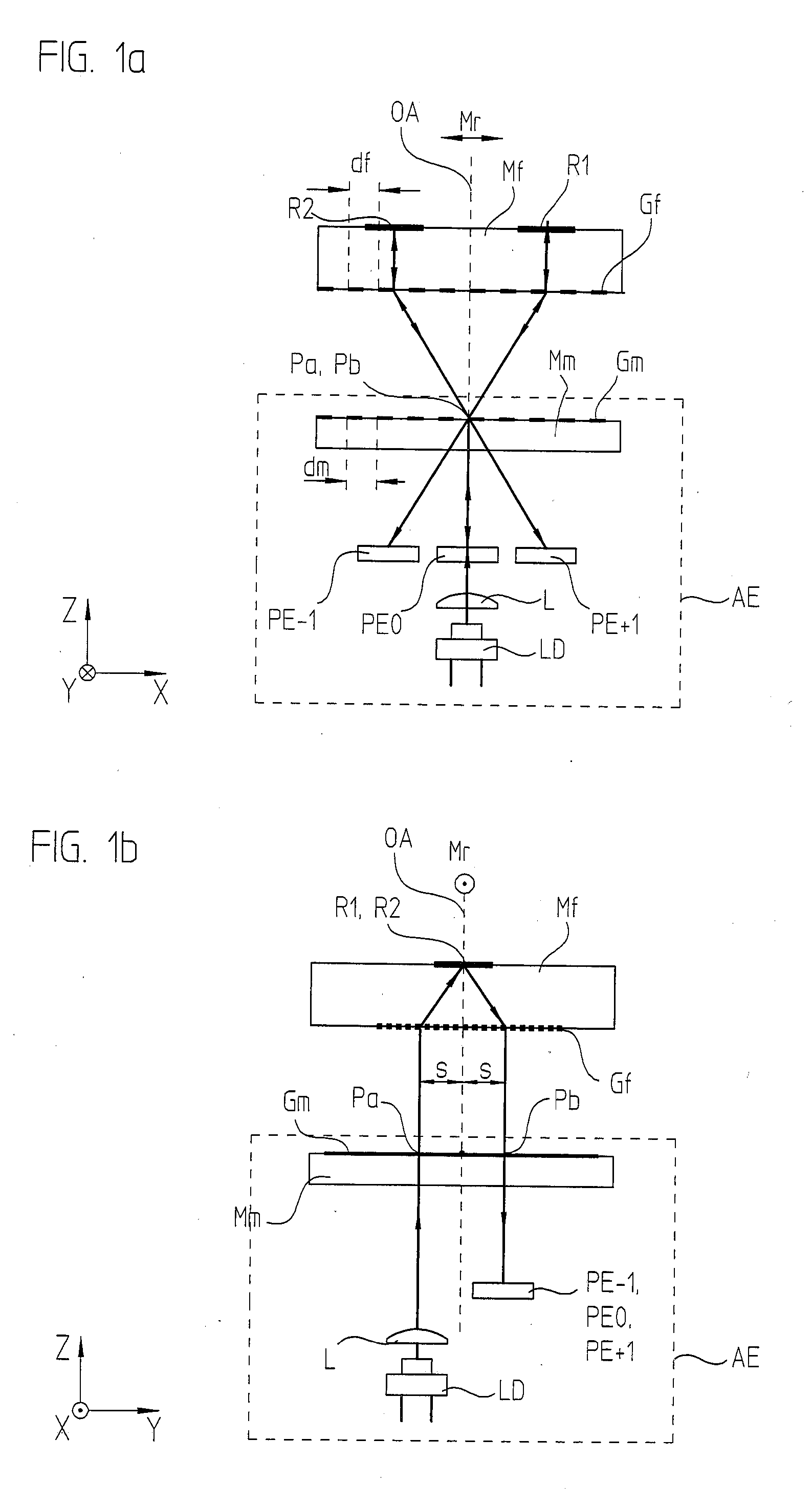
[0008]Because of the lateral offset of the partial beams of rays falling on and exiting the scale, it is possible to dispense with an otherwise necessary oblique illumination of the measuring graduation to separate these partial beams of rays. This results in scanning optics having increased overall symmetry, which leads to substantially greater alignment tolerances.
[0009]The optical position-measuring device makes it possible to record or determine the relative position of a scanning unit as well as a scale movable to it in at least one measuring direction. The scale is configured as a combined unit which includes at least one reflector element and a measuring graduation. A light source and one or more detector elements are assigned to the scanning unit. The scanning unit includes a splitting device which splits the beam of rays, emitted by the light source, into at least two partial beams of rays in the measuring direction, which after being split, propagate in the direction of the scale.
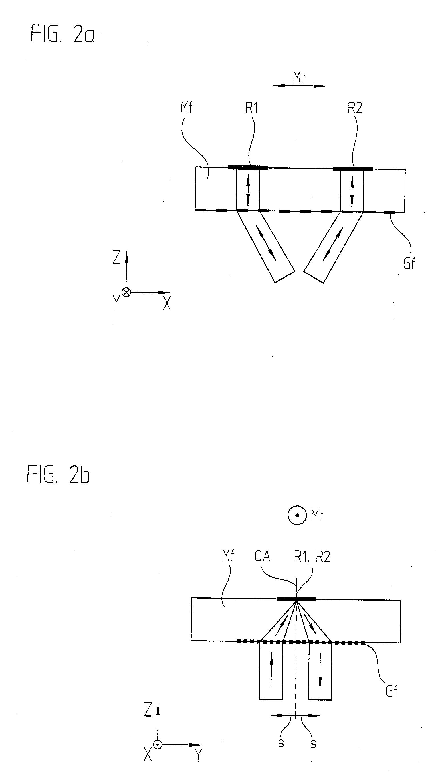
[0014]a second deflection effect on the incoming partial beams of rays results in a direction which is oriented transversely to the measuring direction, a focusing on the at least one reflector element being associated with the second deflection.

Problems solved by technology

In general, the correct mounting of the scanning unit and scale relative to each other proves to be problematic.
The results of such moiré twistings in measuring operation are a decline of the scanning-signal intensity and unwelcome errors in the position measurement.
In the optical position-measuring device, moiré twistings no longer have an erroneous effect on the position measurement and no longer lead to a decline in the intensity of the scanning signal.

Method used


Image

  • Optical position-measuring device
  • Optical position-measuring device
  • Optical position-measuring device

Examples


Embodiment Construction

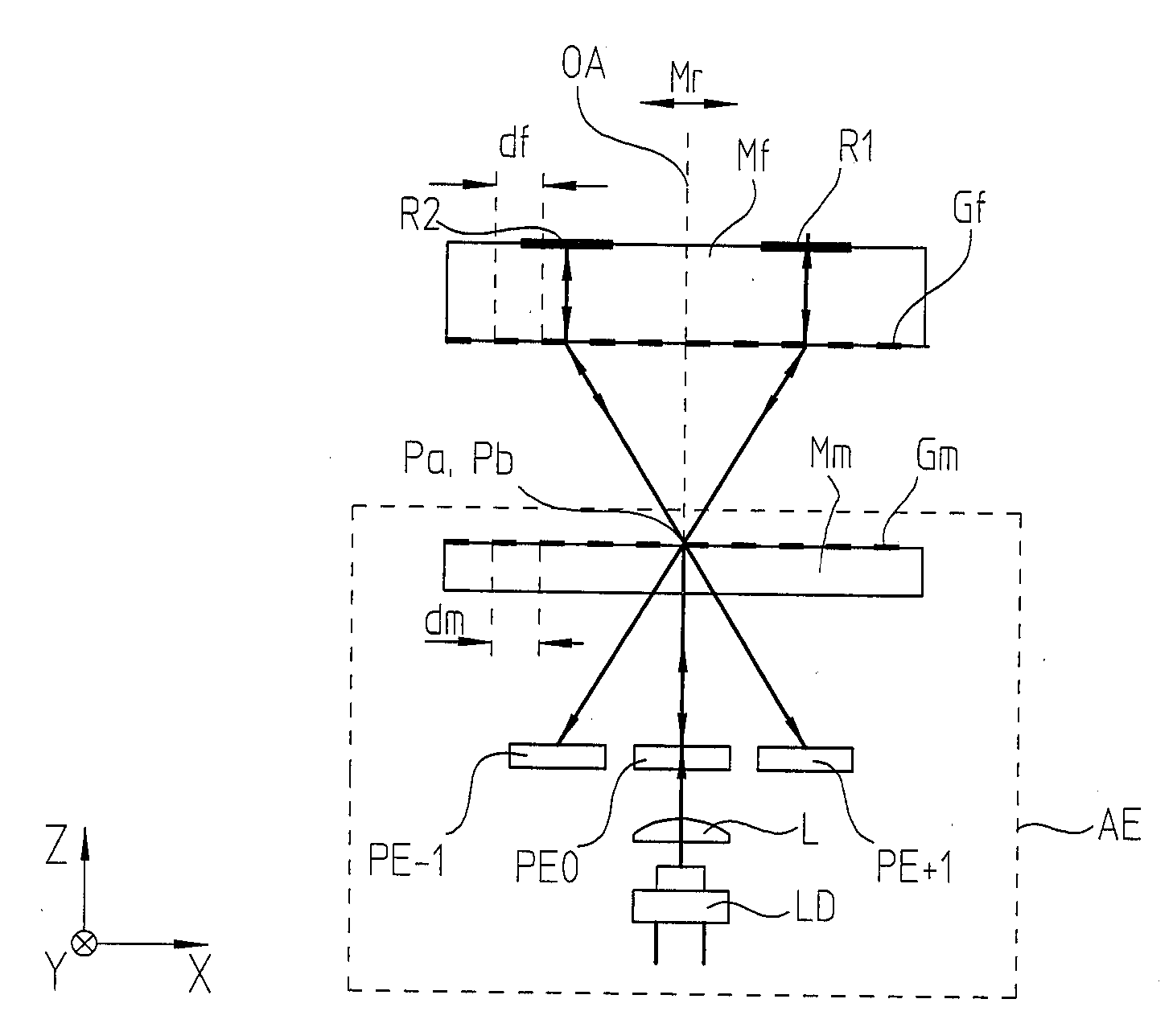
[0041]In the following, a position-measuring device according to an example embodiment of the present invention is explained with reference to FIGS. 1a, 1b, 2a, 2b and 3. FIGS. 1a and 1b show scanning optics of the position-measuring device in different views, the position-measuring device including a scanning unit AE, as well as a scale Mf movable relative to it in measuring direction Mr. Scanning unit AE and scale Mf are joined to the objects whose relative position is to be recorded. For example, they may be two machine parts movable relative to each other.

[0042]Scale Mf of the position-measuring device is in the form of a combined unit which includes two reflector elements R1, R2, as well as a measuring graduation Gf. A light source LD as well as a plurality of detector elements PE−1, PE0, PE+1 are assigned to scanning unit AE. Scanning unit AE also includes splitting device Mm having a transmitted-light scanning grating Gm. As an alternative to the arrangement shown of light so...


PUM


Abstract

An optical position-measuring device is arranged for recording the relative position of a scanning unit and a scale movable to it in at least one measuring direction. The scale is configured as a combined unit which includes at least one reflector element as well as a measuring graduation. A light source and one or more detector elements are assigned to the scanning unit. The scanning unit includes splitting device(s) which split the beam of rays, emitted by the light source, into at least two partial beams of rays in the measuring direction, which after being split, propagate in the direction of the scale.

Description

CROSS-REFERENCE TO RELATED APPLICATIONS[0001]The present application claims the benefit of U.S. Provisional Patent Application No. 60 / 938,271, filed on May 16, 2007, and claims priority to Application No. 10 2007 023 300.2, filed in the Federal Republic of Germany on May 16, 2007, each of which is expressly incorporated herein in its entirety by reference thereto.FIELD OF THE INVENTION[0002]The present invention relates to an optical position-measuring device.BACKGROUND INFORMATION[0003]Conventional optical position-measuring devices for recording the relative position of two movable objects usually include a scanning unit, as well as a scale movable to it in at least one measuring direction. The scanning unit and scale are in each case connected to the two objects, e.g., to machine parts movable relative to each other. In general, the correct mounting of the scanning unit and scale relative to each other proves to be problematic. An unwanted twisting of scale and scanning unit abou...

Claims


Application Information

Patent Timeline
IPC IPC(8): G01B11/14
CPCG01D5/34723G01B11/002G01D5/38
Inventor HOLZAPFEL, WOLFGANG
Owner DR JOHANNES HEIDENHAIN GMBH
Learn More