Thermal management for fluorescent ballast and fixture system

a technology of fluorescent ballast and fixture system, which is applied in the field of illumination arts, can solve the problems of short operational life, inconvenient access to the fixture for ballast replacement, and damage to components

Inactive Publication Date: 2008-11-20
GENERAL ELECTRIC CO
View PDF8 Cites 66 Cited by
  • Summary
  • Abstract
  • Description
  • Claims
  • Application Information

AI Technical Summary

Problems solved by technology

These components can be damaged if subjected to high temperatures.
Such temperatures can compromise the operation of the ballast and result in shorter oper

Method used


Image

  • Thermal management for fluorescent ballast and fixture system
  • Thermal management for fluorescent ballast and fixture system
  • Thermal management for fluorescent ballast and fixture system

Examples


Embodiment Construction

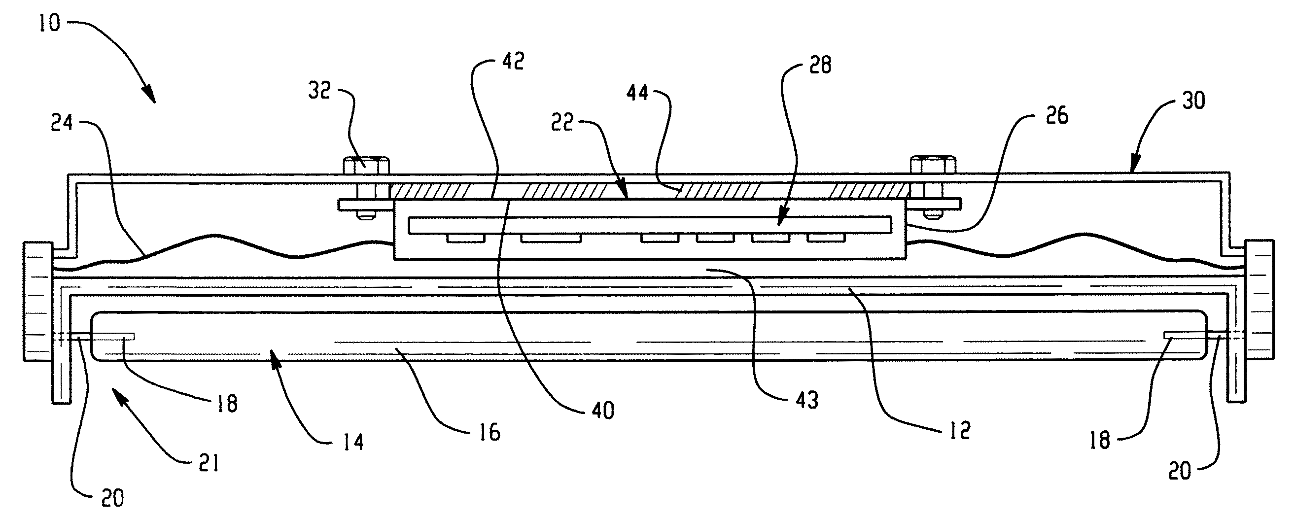
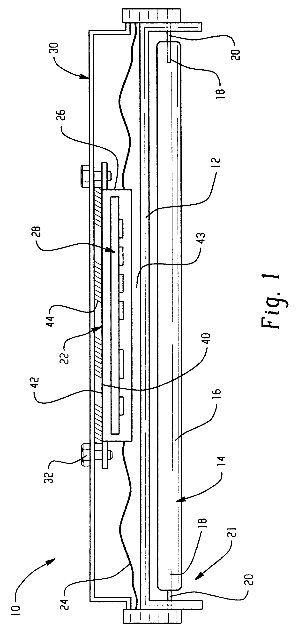
[0009]With reference to FIG. 1, an exemplary lighting assembly includes a fixture 10, such as a fluorescent fixture. The fixture includes a chassis 12 which supports one or more fluorescent lamps 14 which emit light when energized. Each of the lamps 14 may include a tube 16, which encloses a gaseous fill capable of sustaining a discharge between electrodes 18 at opposite ends of the tube. The fill may include a small quantity of mercury with an inert gas, such as argon. A phosphor material may be provided on an interior surface of the tube 16. When the mercury vapor is ionized inside the tube, the lamp discharge emits radiation, including ultraviolet, that in converted to visible light by the phosphor coating. Base pins 20 carry the current to and from the electrodes. The illustrated lamp 14 is a double ended lamp and is supported by the chassis at opposite ends of the lamp. Single ended “Biax” lamps may also be utilized.

[0010]The chassis 12 defines a cavity for receiving the fluore...


PUM


Abstract

A fluorescent lamp assembly includes a fixture which supports at least one fluorescent lamp. A ballast is mounted to the fixture for controlling a supply of electrical current to the fluorescent lamp. A thermal transfer material is interposed between the ballast and a portion of the fixture whereby heat is transferred between the ballast and the fixture.

Description

BACKGROUND OF THE INVENTION[0001]The exemplary embodiment relates to the illumination arts. It finds particular application in connection with thermal management in a ballast for a lighting fixture and will be described with particular reference thereto.[0002]Lighting fixtures, such as those which support fluorescent lamps, typically employ a ballast to control the current supplied to the lamps. Typically, the ballast used for a fluorescent lighting fixture is an electronic ballast. The ballast includes a circuit board which carries components such as filters, rectifiers, and capacitors, for rectifying the AC current input and providing a high voltage during initial start-up of the lamp. These components can be damaged if subjected to high temperatures. Under most operating conditions, however, any heat generated by the ballast is dissipated to the atmosphere via the ballast housing or through the relatively cool fixture and the ballast does not suffer overheating problems.[0003]Flu...

Claims


Application Information

Patent Timeline
IPC IPC(8): F21V29/00H01J9/00
CPCF21V23/026F21V29/85F21V29/74F21V29/004
Inventor THOMAS, EDWARD JOHN
Owner GENERAL ELECTRIC CO
Why Eureka
Try Eureka