Battery pack

Active Publication Date: 2008-11-20
SONY CORP
View PDF5 Cites 14 Cited by
  • Summary
  • Abstract
  • Description
  • Claims
  • Application Information

AI Technical Summary

Benefits of technology

[0011]According to the above embodiment of the invention, the electrode tab is formed with the position matching hole for position matching to the terminal of the battery cell. Therefore, position matching between the electrode tab and the battery cell terminal can be easily carried out utilizi

Problems solved by technology

In such a battery pack, however, in the case of spot welding a copper material electrode tab, the electrical resistivity of copper is very low so that the magnitude of the non-effective shunt current would not materially be changed even when the non-effective shunt current path is elongated by providing a welding slit.
However, in the battery pack in whic

Method used


Image

  • Battery pack
  • Battery pack
  • Battery pack

Examples


Embodiment Construction

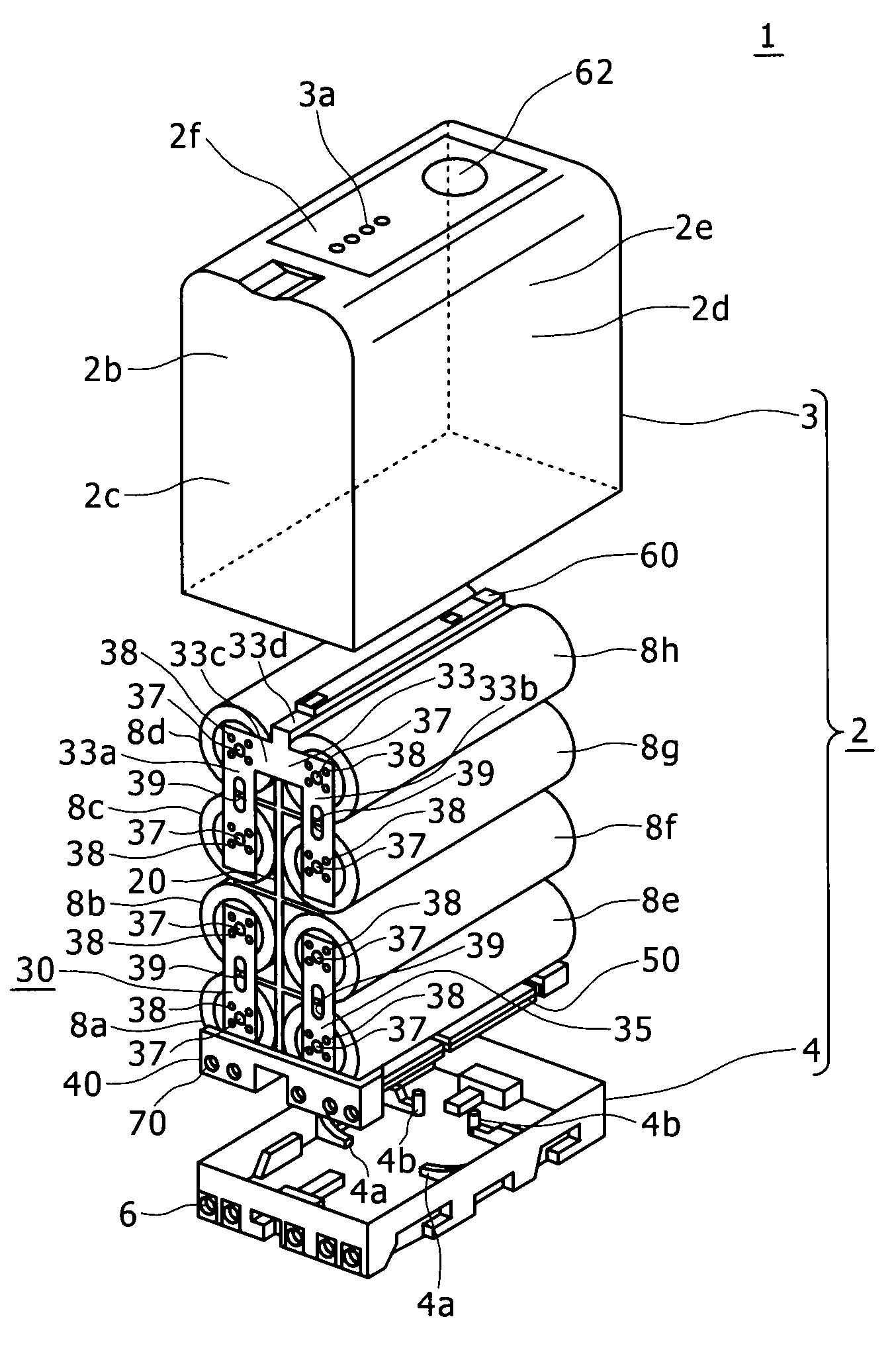
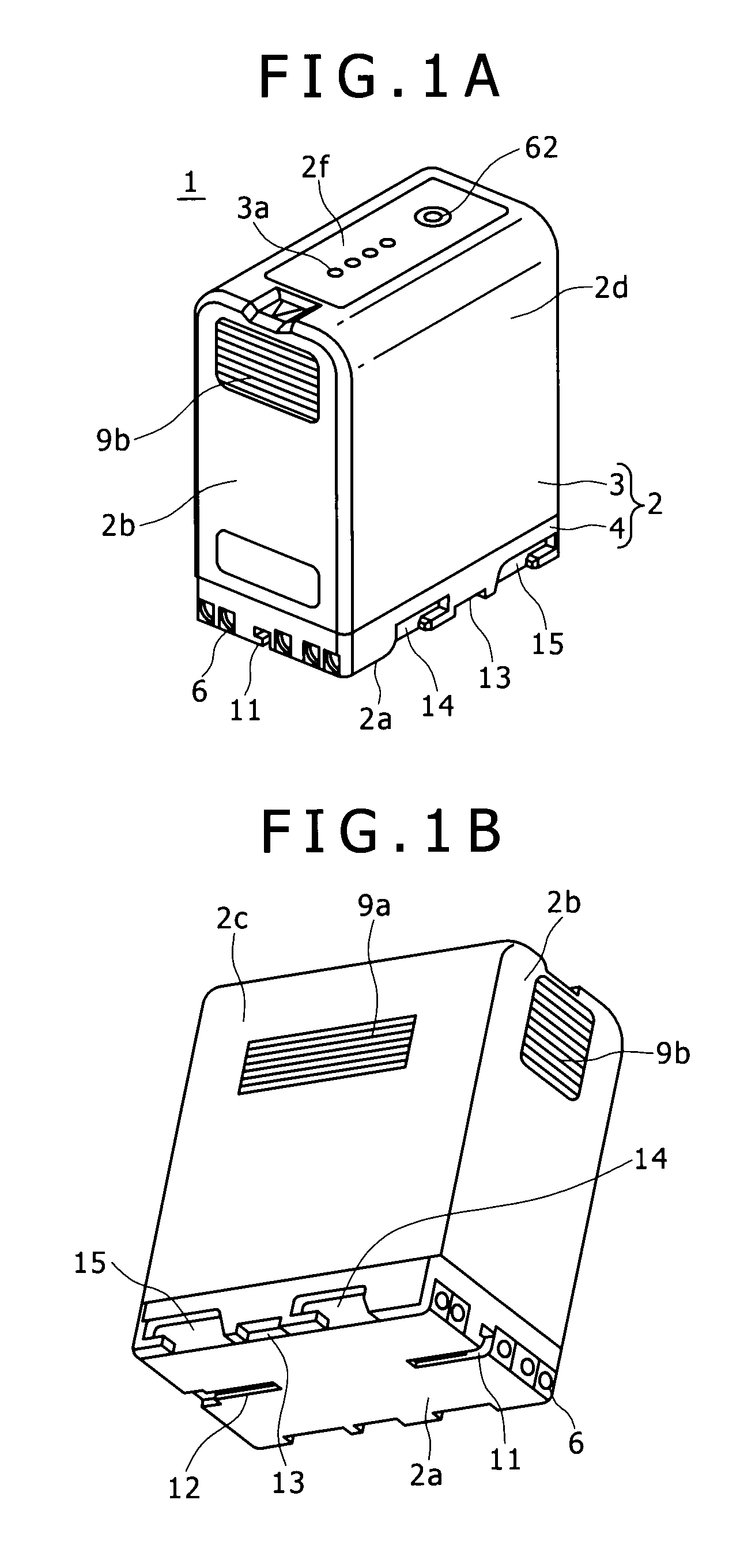
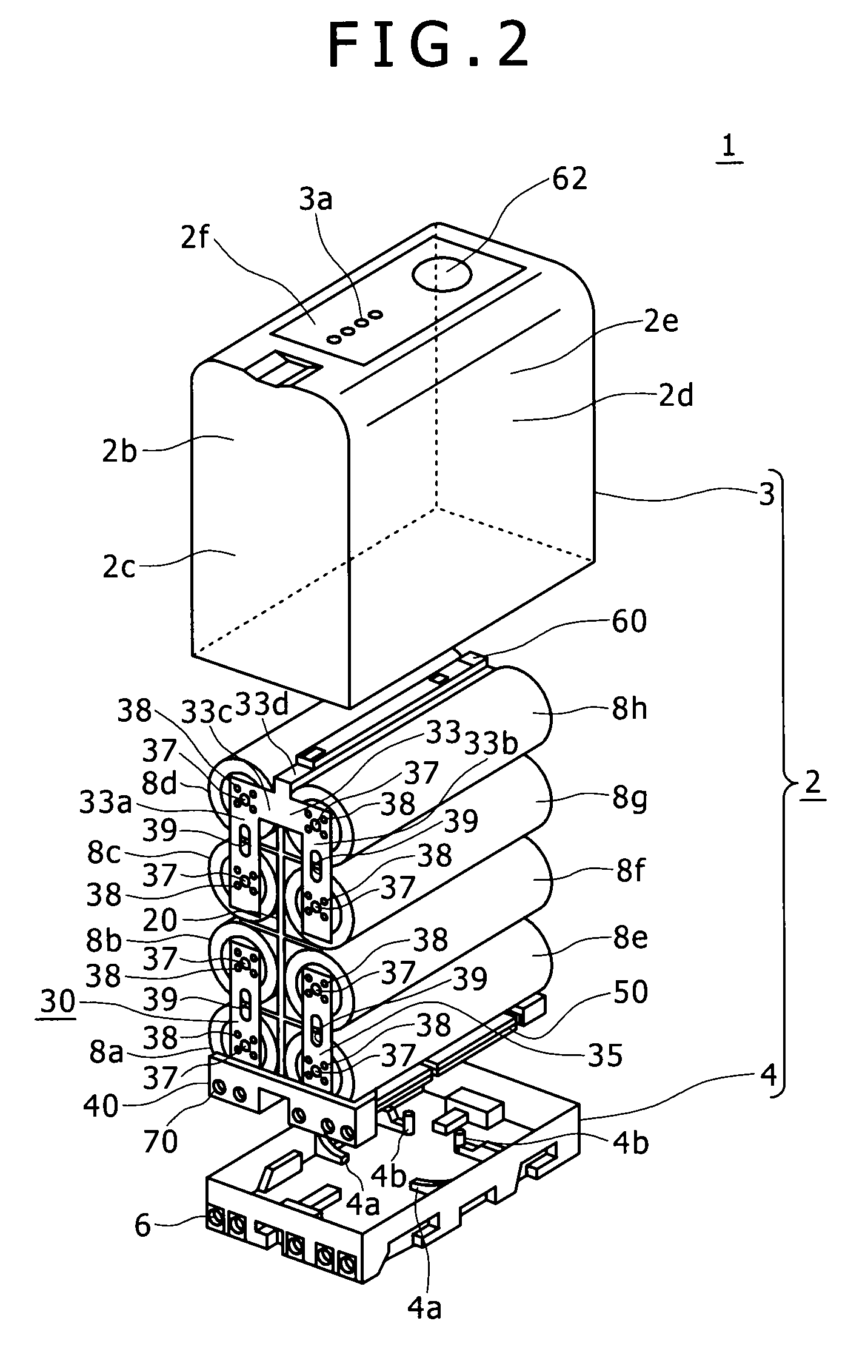
[0048]Now, a battery pack based on the present invention will be described in detail below, referring to the drawings. The battery pack based on the present invention is prepared in two kinds, according to the number of battery cells 8 contained in a casing 2, for example, an L-size battery pack 1 shown in FIGS. 1A, 1B and 2 and an S-size battery pack 100 shown in FIGS. 3A, 3B and 33. Specifically, the L-size battery pack 1 contains eight battery cells 8a to 8h (hereinafter, the battery cells 8a to 8h will also be referred to simply as the battery cells 8) in two rows and four layers as shown in FIG. 2, while the S-size battery pack 100 contains four battery cells 8i to 8l (hereinafter, the battery cells 8i to 8l will also be referred to simply as the battery cells 8) in two rows and two layers as shown in FIG. 33. The battery packs 1, 100 based on the present invention each have a roughly rectangular casing 2 in which the battery cells 8 are contained and which has a terminal part ...


PUM


Abstract

Disclosed herein is a battery pack including: a plurality of cylindrical battery cells; and an electrode tab for electrically connecting terminals of the battery cells arranged in a pattern; wherein the electrode tab is formed with a position matching hole for position matching to the terminal of the battery cell, at a fixation part for fixation to the terminal of the battery cell.

Description

CROSS REFERENCES TO RELATED APPLICATIONS[0001]The present invention contains subject matter related to Japanese Patent Application JP 2007-130886 filed in the Japan Patent Office on May 16, 2007, the entire contents of which being incorporated herein by reference.BACKGROUND OF THE INVENTION[0002]1. Field of the Invention[0003]The present invention relates to a battery pack with which it is possible to enhance productivity of a welding work.[0004]2. Description of the Related Art[0005]A battery pack includes a plurality of cylindrical battery cells, electrode tabs for electrically connecting terminals of the battery cells arranged in a certain pattern, a lower case for containing the battery cells electrically connected through the electrode tabs, and an upper cover for covering the lower case containing the battery cells therein, and is detachably attached to a body of an electronic apparatus, to be used as a power source for the electronic apparatus (refer to Japanese Patent Laid-O...

Claims


Application Information

Patent Timeline
IPC IPC(8): H01M2/10H01M50/179H01M50/51H01M50/512H01M50/516H01M50/522
CPCH01M2/06H01M2/204H01M2/105Y02E60/10H01M50/213H01M50/51H01M50/522H01M50/516H01M50/512H01M50/179
Inventor YUSA, TAKAHIRONAITO, MASAKAZU
Owner SONY CORP
Why Eureka
Try Eureka