
Connector

a connector and connector technology, applied in the direction of coupling device connection, instruments, computing, etc., can solve the problems of increasing the number of contacts, requiring the connector to be made larger, and the anchoring portion of the connector is susceptible to detachment or breakage, so as to improve the degree of freedom of wiring

Inactive Publication Date: 2008-11-20
FRAMATOME CONNECTORS INT SA
View PDF7 Cites 11 Cited by
  • Summary
  • Abstract
  • Description
  • Claims
  • Application Information

AI Technical Summary

Benefits of technology

[0005]Therefore, the present applicant performed diligent research toward solving the above problems, and discloses a cable-type connector wherein the information device is not completely anchored as in conventional devices, having a freely movable structure (known as “floating” below) within a certain two-dimensional or three-dimensional partition, enabling the connectors to be connected with little insertion force at the electronic circuit board side, and being of compact size.
[0014]In this case, if the connection between the information device side connector of the cable-type connector and the information device side counterpart connector is such that the information device is not anchored inside the computer device by anchoring means, such as when the information device is in a state of rest on the flat surface of the casing of the computer device, then there is no need to separately provide an anchoring portion for anchoring the information device, thus allowing efficient use of the interior space and further eliminating the load on the anchoring portion due to the insertion force of the cable-type connector as discussed in the above-described problems.
[0016]On the other hand, in the connection between the electronic circuit board side connector of the cable-type connector and the counterpart connector mounted on the electronic circuit board, the contacts arrayed on the electronic circuit board side connector of the cable-type connector can be wired with fewer contacts than the information device side connector as mentioned above. As a result, since the insertion force of a cable-type connector into a counterpart connector anchored on a electronic circuit board can be determined by the frictional force between contacts provided in the electrically contacting connectors, if the number of contacts is reduced as compared with the number of contacts necessary in conventional wiring, then the insertion force can be correspondingly reduced, while also enabling the cable to be made more compact due to the reduction in number of contacts.
[0019]For example, an information device itself having an information device side counterpart connector to be connected to a cable-type connector has a structure such as to be positioned so as to be freely movable (floating) within an arbitrary two-dimensional or three-dimensional partition inside a computer device, thereby enabling partitions to be formed using a simpler method than in the case where the information device is anchored, thus improving the degree of freedom of the information device.
[0024]Additionally, the connectors at the ends of the cable-type connector of the present invention have at least one control signal contact and at least one power contact terminally wired from the above two types of cables. As for the respective configurations, an information device side connector of a cable-type connector in a power cable might be electrically connected to a single cable sharing a plurality of power contacts to which the same voltage is applied, and an electronic circuit board side connector of a cable-type connector might have contacts connected in a one-to-one correspondence to each cable. Additionally, on the information device side of the cable-type connector in a control signal cable, wiring is performed with one contact per cable line, and in the electronic circuit board side connector, at least one drain line is connected to the shield covering the contacts, thus allowing for a contact configuration that reduces the number of terminals while keeping the performance constant.
[0026]In the electronic circuit board side connector, a specific, independent structure such that the number of contacts of the electronic circuit board side connector is fewer than the number of contacts of the hard disk device side connector can be employed for both the control signal cable and power cable, so that if the connectors are connected on the electronic circuit board side using the two types of connectors of a connector wired with only power lines and a connector wired with only control signal lines, then the power lines and signal lines can be separately wired on the electronic circuit board, thus improving the degree of freedom of wiring on the electronic circuit board.

Problems solved by technology

With this connector connection, the insertion force for connecting the connectors depends on the frictional force of each contact and the number of contacts, and there is a one-to-one correspondence between the contacts of the information device side connector and the contacts of the electronic circuit board side connector, so an increase in the number of contacts may be accompanied by an increased load on the anchoring portions of the electronic circuit board side connector at the time of insertion, thus making the connector anchoring portions susceptible to detachment or breakage, and also requiring the connector to be made larger.

Method used


Image

  • Connector
  • Connector
  • Connector

Examples


first embodiment

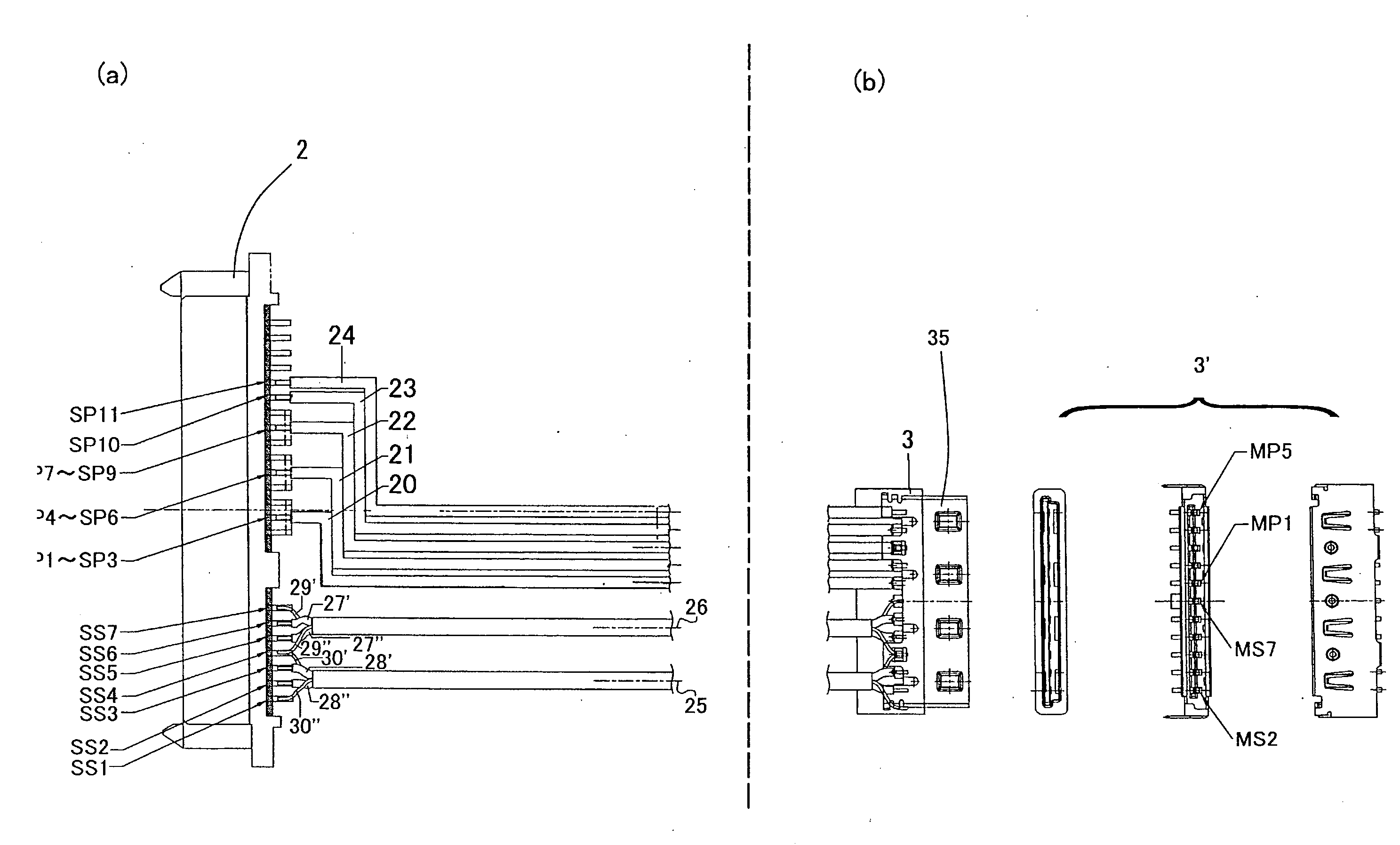
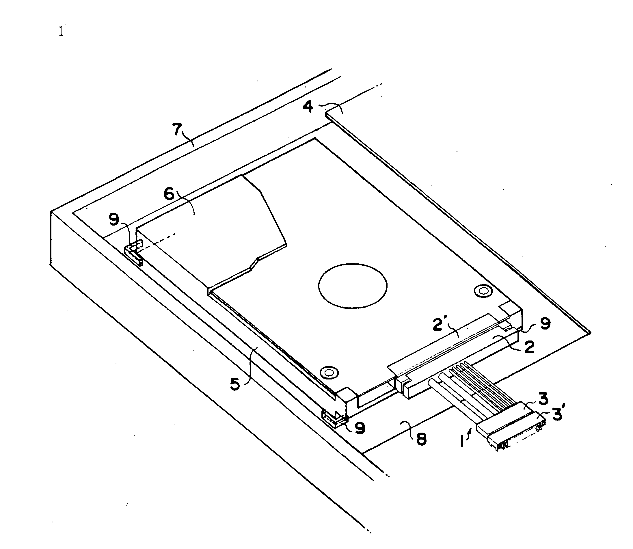
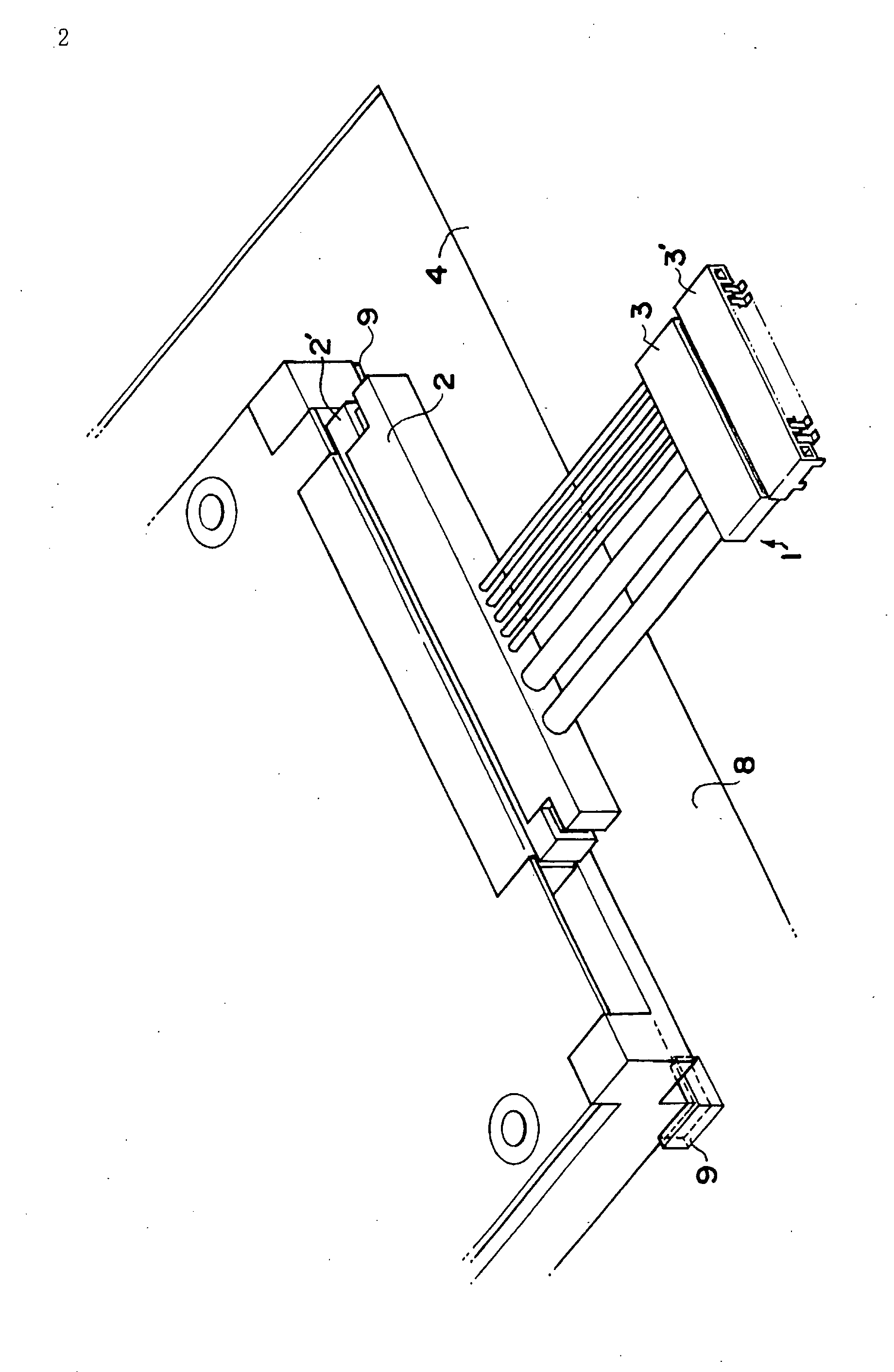
[0073]FIG. 1 shows an overall perspective view of how a cable-type connector 1 according to the present invention is connected at one end to a counterpart connector 2′ on a hard disk device side and at the other end to a counterpart connector 3′ mounted on an electronic circuit board 4, thus configuring the electrically connected components to transmit control signals or the like from the microprocessor to the hard disk device. The hard disk device 5 has wiring with lines for power and control signals that are not shown, such as wiring in a circuit board, the lines being connected to a corresponding plurality of contacts (not shown) arrayed inside a connector (counterpart connector 2′ to the hard disk side connector 2 of the cable-type connector) formed at an edge of the hard disk housing 6. Additionally, on the electronic circuit board 4 is provided a connector (counterpart connector 3′ to the electronic circuit board side connector 3 of the cable-type connector) having therein an ...

second embodiment

[0079]FIG. 6 shows a side view of a connection between a counterpart connector on a hard disk device side and a counterpart connector on the electronic circuit board side using a cable connector 11 according to the present invention.

[0080]FIG. 7 shows a cable-type connector 22 according to a third embodiment of the present invention. While the connector 2 and counterpart connector 2′ on the hard disk device side (a) and the connector 3a and counterpart connector 3′a on the electronic circuit board side (b) are the same as in the second embodiment, the shapes of the power line connector 3c and counterpart connector 3c′ on the electronic circuit board side (b) are different. When the contacts of the connector 3c are seen from a direction parallel to the electronic circuit board, there are two symmetrical rows of five cables each for a total of ten, and the contacts are pin-shaped to form a plug-type connector. The counterpart connector 3c′ is a socket-type connector, and as shown in F...

third embodiment

[0081]FIG. 8 is a side view wherein the counterpart connector 2′ on the hard disk device side and the counterpart connectors 3a′, 3c′ of the electronic circuit board side are connected with a cable connector 22 according to the present invention.

[0082]As described above, the cable-type connector of the present invention for the purpose of electrically connecting an information device side such as a hard disk or the like and an electronic circuit board side has two types of cables for power and control signals, reducing the number of cables by sharing a plurality of contacts connected to the power lines of the information device side connector with a singe cable, and reducing the contacts on the electronic circuit board side connector by connecting at least one drain line of the control signal cables containing a pair of signal lines and a pair of drain lines to a shield. Therefore, when comparing the information device side and the electronic circuit board side, the number of both p...


PUM


Abstract

A connector for electrically connecting a primary side mating connector having contacts and a secondary mating connector having contacts. The connector has parallelly arranged flexible cables and connectors provided at both ends of the cable and individually connected to the primary and secondary mating connectors. The number of the primary side contacts is less than the number of the secondary side contacts, and at least some of the secondary side contacts are connected to one cable that is shared by a set of contacts. The primary side mating connectors are fixed on a circuit board. The secondary mating connector is assembled in an information device that is movable on a mounting surface.

Description

TECHNICAL FIELD[0001]The present invention relates to a cable type connector and connector connection structure for interconnecting connectors on a primary device side and a secondary device side, and particularly relates to a cable-type connector for connecting a primary side comprising a control-side electronic circuit board and a secondary side comprising an information device in a personal computer.BACKGROUND ART[0002]Generally, computer devices such as personal computers and laptop computers comprise an electronic circuit board on which are mounted devices such as memory or a microprocessor for performing computations, and an externally connectable information device separate from the electronic circuit board. Normally, when electrically connecting the electronic circuit board side and the information device side, an information device side connector having an array of contacts connected to given cables or wires for operating the information device is mounted on a portion of th...

Claims


Application Information

Patent Timeline
Patent Type & Authority Applications(United States)
IPC IPC(8): H01R12/24
CPCG06F1/184G06F1/187H01R13/65802H01R23/7073H01R31/06H01R12/714H01R13/6581H01R12/77H01R13/631
Inventor KAMEDA, YASUTOSHI
Owner FRAMATOME CONNECTORS INT SA
Learn More