
Image detecting system, image detecting method and computer readable medium

Inactive Publication Date: 2008-11-20
FUJIFILM CORP
View PDF4 Cites 7 Cited by
  • Summary
  • Abstract
  • Description
  • Claims
  • Application Information

AI Technical Summary

Benefits of technology

[0007]Therefore, it is an object of an aspect of the innovations herein to provide an image detecting system, an image detecting method and a computer readable medium which are capable of overcoming the above drawbacks accom

Problems solved by technology

These techniques, however, cannot reveal how blood is supplied to a tissue.
For this drawback, the above-described techniques cannot easily identify a tissue that is fed by blood, for example, a tumor.

Method used


Image

  • Image detecting system, image detecting method and computer readable medium
  • Image detecting system, image detecting method and computer readable medium
  • Image detecting system, image detecting method and computer readable medium

Examples


Embodiment Construction

[0017]Some aspects of the invention will now be described based on an embodiment, which does not intend to limit the scope of the present invention, but exemplifies the invention. All of the features and the combinations thereof described in the embodiment are not necessarily essential to the invention.

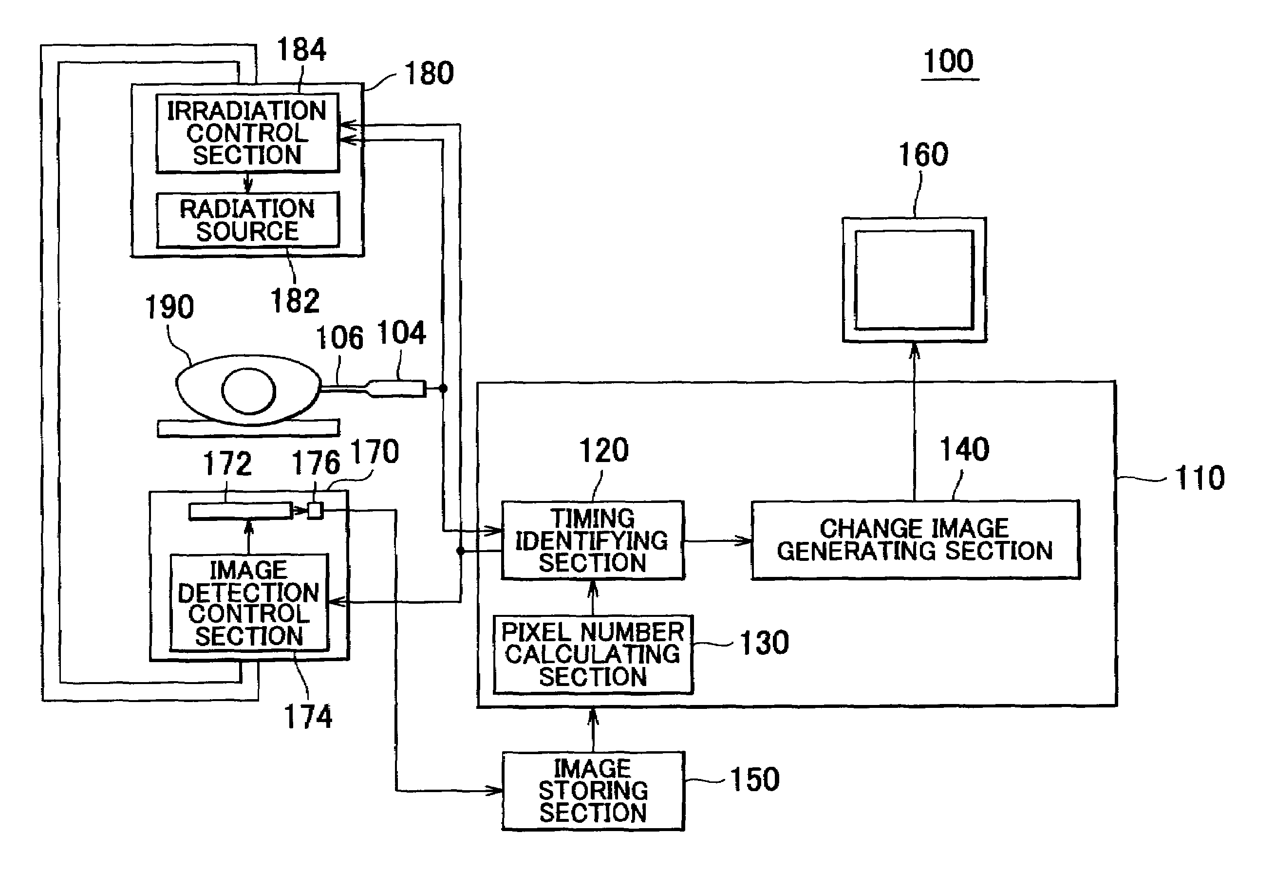
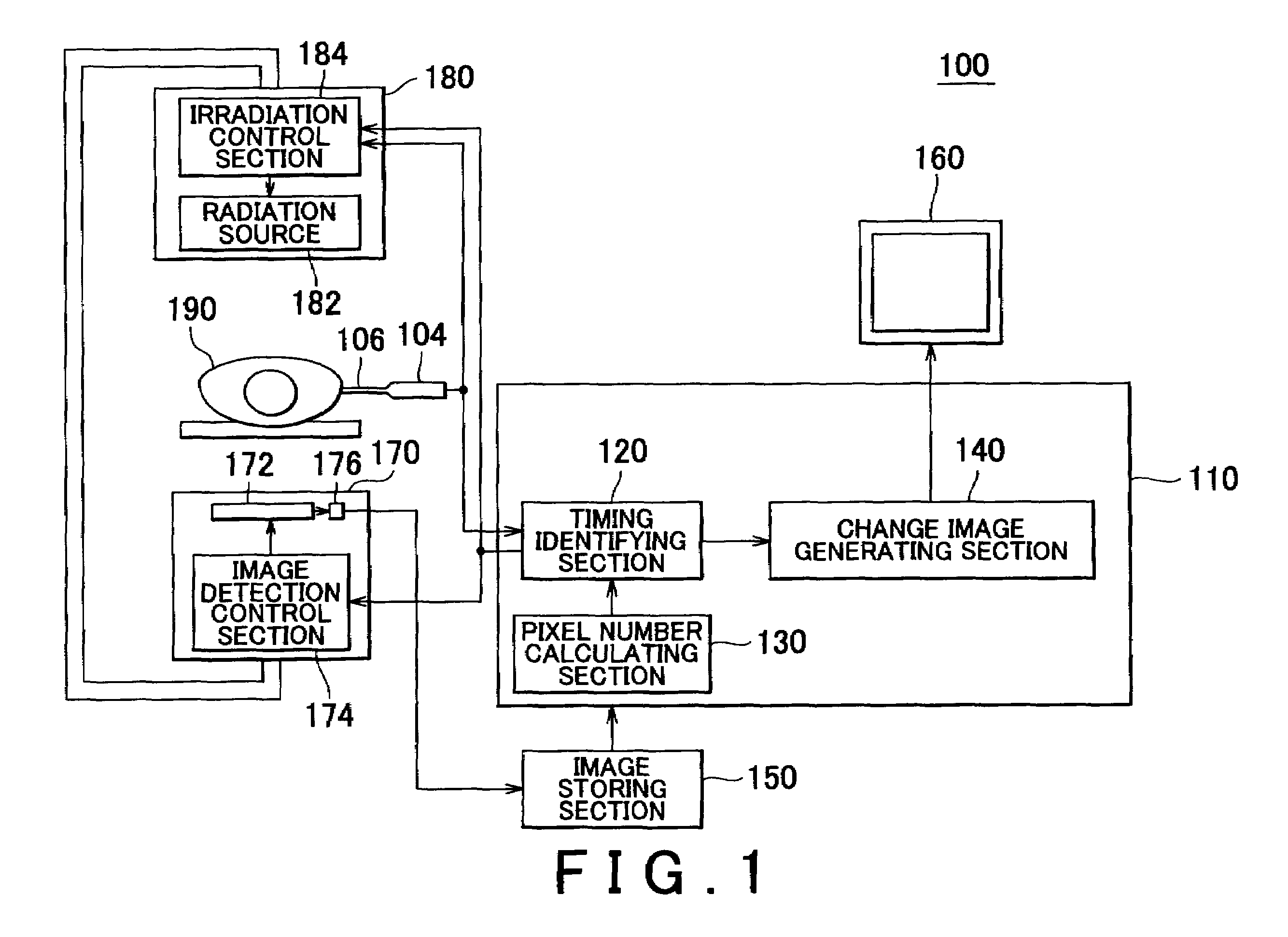
[0018]FIG. 1 illustrates an example of a radiation image detecting system 100 relating to an embodiment of the present invention, together with an examination subject 190. The radiation image detecting system 100 detects a change image of the examination subject 190 into which a radiopaque contrast medium has been injected, by using radiation. The radiation image detecting system 100 includes an image processing apparatus 110, an image storing section 150, a display section 160, a radiation image detecting section 170, a radiation generating section 180, a radiopaque contrast medium injector 104, and a catheter 106. The radiation generating section 180 generates radiation to be irradi...


PUM


Abstract

There is provided an image detecting system including an image detecting section that detects a moving image of an examination subject into which a radiopaque contrast medium flows through one of an artery and a portal vein, and a change image generating section that generates a change image representing a change in the moving image. Here, the change is caused by movement of the radiopaque contrast medium after a timing at which the radiopaque contrast medium that has flown into one of the artery and the portal vein flows into capillaries.

Description

CROSS REFERENCE TO RELATED APPLICATION[0001]The present application claims priority from a Japanese Patent Application No. 2007-132682 filed on May 18, 2007, the contents of which are incorporated herein by reference.BACKGROUND[0002]1. Technical Field[0003]The present invention relates to an image detecting system, an image detecting method and a computer readable medium. More particularly, the present invention relates to a radiation image detecting system and a radiation image detecting method for detecting an image by using radiation, and to a computer readable medium for use with the radiation image detecting system.[0004]2. Related Art[0005]A known blood flow analysis apparatus calculates a ratio or difference between a parameter indicating hemodynamics unique to a tissue of an examination subject and a parameter indicating hemodynamics unique to a desired reference region, where the parameters indicate the hemodynamics based only on the time density curves of the tissue and th...

Claims


Application Information

Patent Timeline
IPC IPC(8): A61B5/026
CPCA61B5/4244A61B6/507A61B6/504A61B6/481
Inventor OHTA, YASUNORIUEDA, KAZUHARUAOYAMA, TATSUYAYODA, AKIRA
Owner FUJIFILM CORP
Learn More