Apparatus, system and method for generating bubbles on demand

a technology of apparatus and bubbles, applied in the field of apparatus, system and method for generating bubbles on demand, can solve the problems of extremely expensive equipment, human health risk, and the sound waves used during ultrasound procedures, but are relatively risk-free, and achieve the effect of facilitating a wide variety of imaging techniques and therapeutic procedures

Inactive Publication Date: 2004-12-16
BAYER HEALTHCARE LLC
View PDF21 Cites 121 Cited by
  • Summary
  • Abstract
  • Description
  • Claims
  • Application Information

AI Technical Summary

Benefits of technology

[0021] Another related objective is to create a system and / or method of generating a microbubble contrast medium whose properties can be controlled in a way that facilitates a wide variety of imaging techniques and therapeutic procedures.

Problems solved by technology

Although other techniques (e.g., computerized tomography (CT), positron emission tomography (PET), magnetic resonance imaging (MRI) and magnetic resonance angiography (MRA)) can be used to produce images of the body, they do so using extremely expensive equipment.
In addition, although CT and PET scanning techniques are considered reasonably safe, they obtain images using ionizing radiation, which can pose a risk to human health particularly upon repeated exposure.
The sound waves used during an ultrasound procedure, however, are comparatively risk free.
If the acoustic impedance difference is too great, however, a good image may not be created because too much energy is reflected.
Though such spheres have a shell that is hard compared to a liquid, they are very small and relatively fragile.
Solid particles are therefore not as efficient or effective as scatterers of ultrasonic energy.
There are several disadvantages inherent to the prior art practices described above.
Variations in the preparation process (e.g., mixing, agitation, pressure activation, etc.) can lead to variations in the concentration and size distribution of the microspheres or particles within the contrast medium, which can adversely affect the resulting imaging procedure.
There can also be degradation from storage of the delicate powders.
After preparation, most contrast agents deteriorate over time, causing the concentration of the microbubbles or particles to decrease and their size to vary with time.
Contrast agents in the form of microbubbles are also adversely affected by pressure before or during administration.
Gas can also diffuse into a microbubble, causing it to grow unacceptably large.
These problems affect the concentration and the size of the microbubbles within the contrast medium.
Microbubbles are mechanically fragile and thus can be destroyed during both injection and storage.
The pressure at which the injections are currently given must be severely limited to prevent destruction of the microbubbles.
This leads to non-uniform or even non-diagnostic bubble densities.
Another shortcoming of the prior art practice relates to the limited lifetime of such contrast media and the need for sterile conditions in handling and administration.
When the imaging procedure requires less contrast media than what a vial provides, the unused portion is routinely discarded, which represents a waste of money.
Not only does this prove inconvenient and distracting to the technologist, it takes a significant amount of time, which also translates into increased costs.
There are several difficulties with this method, however.
First, access has to be gained to the particular vessel to be imaged, because bubbles of carbon dioxide will not reliably travel through the lungs.
Second, there is no way to measure or monitor the number or size distribution of the bubbles being created.
If these bubbles were created with any gas other than carbon dioxide, they would represent a significant hazard to the patient, as it would pose a risk of embolization or blockage of vessels and capillaries downstream.
Lastly, if there is any failure, large bubbles of CO.sub.2 might be created in the blood vessel.
They can, however, disturb the flow of blood and thus disrupt the imaging procedure.
Thus, there are significant drawbacks and limitations to the apparatus and method disclosed by Daum et al.

Method used


Image

  • Apparatus, system and method for generating bubbles on demand
  • Apparatus, system and method for generating bubbles on demand
  • Apparatus, system and method for generating bubbles on demand

Examples


first embodiment

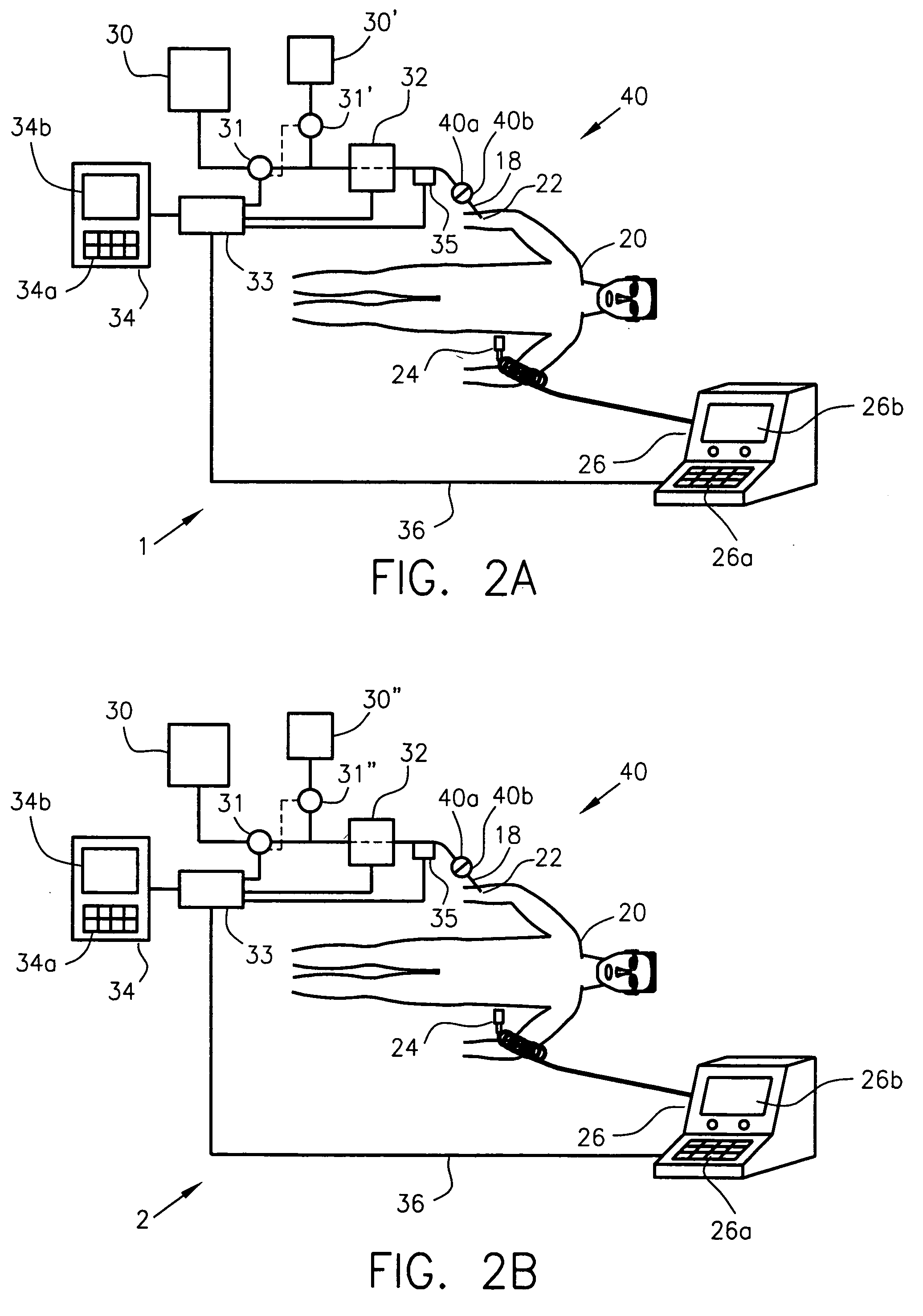
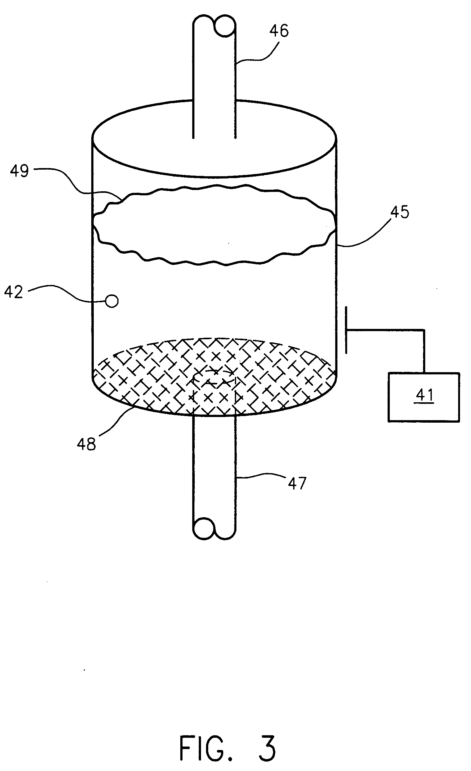
[0069] FIG. 3 illustrates the microbubble generator, one capable of generating microbubbles on demand when incorporated within the disclosed systems 1 and 2. It employs a gas-liquid interface and a means of disrupting that interface to create microbubbles of the desired diameter. More specifically, the microbubble generator includes an enclosure 45, a mechanism 41 for agitating the enclosure, two fluid path conduits 46 and 47 and, preferably, a filter 48. Designed to withstand the forces associated with vigorous shaking, the enclosure 45 is the container within which to agitate the liquid in the presence of a gas. The agitating mechanism 41 can be manifested in any number of ways, such as something akin to a dental amalgam mixer. Fluid path conduits 46 and 47 are preferably made from a flexible material. They should possess a degree of flexibility sufficient to permit container 45 to be shaken during normal operation without suffering any damage to either itself or its associated fl...

third embodiment

[0077] FIGS. 5A and 5B illustrate the microbubble generator. It too employs a gas-liquid interface and a means of disrupting that interface to create microbubbles of the appropriate diameter. More specifically, the microbubble generator includes an enclosure 56, a stirring element 59, a mechanism 57 for rotating the stirring element, two fluid path conduits 46 and 47 and, preferably, a filter 48. Enclosure 56 is the container in which the interaction between the liquid and gas takes place. Situated within enclosure, stirring element 59 is preferably submerged only partially in the liquid. Situated near the outlet conduit 47, filter 48 can again be implemented in any of the ways described in connection with the previous embodiments, including active filtering.

[0078] Stirring element 59 can be implemented as a partially coiled wire loop, a whisk or various other beating elements. For example, as shown in FIG. 5B, the stirring element may be composed of multiple small wires, as denoted...

fourth embodiment

[0084] FIG. 6 depicts the essential details of microbubble generator, one built to operate as part of the disclosed systems 1 and 2. More specifically, this microbubble generator includes a passage or nozzle 60 or an array of such nozzles. Preferably cylindrical in shape, the nozzle 60 features a plurality of nucleation sites. Each nucleation site 61 can take the form of a pit several microns in diameter, preferably on the order of 3 to 100 .mu.m. Each pit is formed in the inner wall of the nozzle 60, and would ideally be deep enough and of a profile such that the liquid does not wet down to the bottom during normal handling and preparation. Several alternative geometries are possible. Instead of a planned arrangement or layout of pits, the pattern of pits could be randomized.

[0085] Equipped with a microbubble generator of the type shown in FIG. 6, the systems of FIGS. 2A and 2B would operate generally as follows. In response to a control signal from controller 33, the pump 31 would...


PUM


Abstract

An apparatus, system or method enables microbubbles to be created on demand for use as the contrast agent within a contrast medium administrable to a patient for purposes of a medical procedure. The system comprises a reservoir, a pressurizing device, a microbubble generator, and a controller. The reservoir stores a liquid. The pressurizing device conveys the liquid, along with the medium formed therewith, through the system. The microbubble generator is used to create the microbubbles within the liquid to form the medium. The microbubble generator has an inlet for receiving the liquid and an outlet for communication of the medium to the patient. The controller controls the operation of the system so that the microbubbles created by the microbubble generator are generated according to the demands of the medical procedure and are administrable within the medium to the patient.

Description

CROSS-REFERENCE TO RELATED APPLICATION(S)[0001] This application claims the benefit of U.S. Provisional Application 60 / 351,923 titled Apparatus, System And Method For Generating Bubbles On Demand, filed Jan. 25, 2002; U.S. application Ser. No. 10 / 352,392 titled Apparatus, System And Method For Generating Bubbles On Demand, filed Jan. 27, 2003; and PCT / US03 / 18445 titled Apparatus, System And Method For Generating Bubbles On Demand, filed Jun. 10, 2003. These provisional, non-provisional and international applications have been assigned to the assignee of the invention disclosed below, and their teachings are incorporated into this document by reference.[0002] The invention generally relates to bubble contrast media of the type used for diagnostic imaging and therapeutic procedures. More particularly, the invention relates to apparatuses, systems and methods for preparing on demand, for injection into a patient, bubble contrast media for obtaining high contrast images of the anatomy o...

Claims


Application Information

Patent Timeline
Patent Type & Authority Applications(United States)
IPC IPC(8): A61KA61K49/22A61M5/00A61M5/142A61M5/145A61M5/165A61M5/168
CPCA61K49/223A61M5/007A61M5/142A61M5/145A61M5/165A61M5/16831A61M2005/006A61M2205/11A61M2230/30A61B8/4281
Inventor UBER, ARTHUR E. IIIGRIFFITHS, DAVID M.
Owner BAYER HEALTHCARE LLC
Why Eureka
Try Eureka