Method of rapid hole transfer to replacement parts

a technology of replacement parts and rapid transfer, applied in the field of aircraft maintenance, can solve the problems of limiting mate drilling, ineffective traditional prior art approaches, and inability to precisely mate the replacement parts, so as to reduce the cost of quality, reduce labor costs, and efficiently mate new parts

Active Publication Date: 2008-11-27
THE BOEING CO
View PDF5 Cites 13 Cited by
  • Summary
  • Abstract
  • Description
  • Claims
  • Application Information

AI Technical Summary

Benefits of technology

[0008]Advantageously, new replacement parts may be marked with precise locations captured as a digital definition of “as-built” holes on existing hardware, solving a common and widespread problem felt across the aircraft industry. Laser projection quickly and accurately projects hole feature targets, projected / printed on new parts, to efficiently mate new parts to existing needs. Furthermore, holes may be collected and transferred to a new piece outside of the aircraft to reduce labor costs. Even normally unavailable holes with little or no in place access can be accurately transferred to new parts prior to installation and the parts installed with all holes accurately reproduced on the new parts to reduce “Cost of Quality.”

Problems solved by technology

Consequently, it is unlikely that replacement parts are pre-drilled to exactly match existing parts in the field and typically require custom drilling in existing parts and / or structure.
Traditional prior art approaches (e.g., what is known as mate-drilling), frequently have been ineffective.
Access restrictions can limit mate drilling, especially where existing holes are inaccessible and operator fatigue can provide less than satisfactory results, e.g., from missed holes or improper alignment.
Finding satisfactory work-arounds or correcting errors can increase cycle time and reduce hole quality.
Consequently, this has become a significant cost problem and a schedule driver, especially on large applications such as wing skin replacements.

Method used


Image

  • Method of rapid hole transfer to replacement parts
  • Method of rapid hole transfer to replacement parts
  • Method of rapid hole transfer to replacement parts

Examples


Embodiment Construction

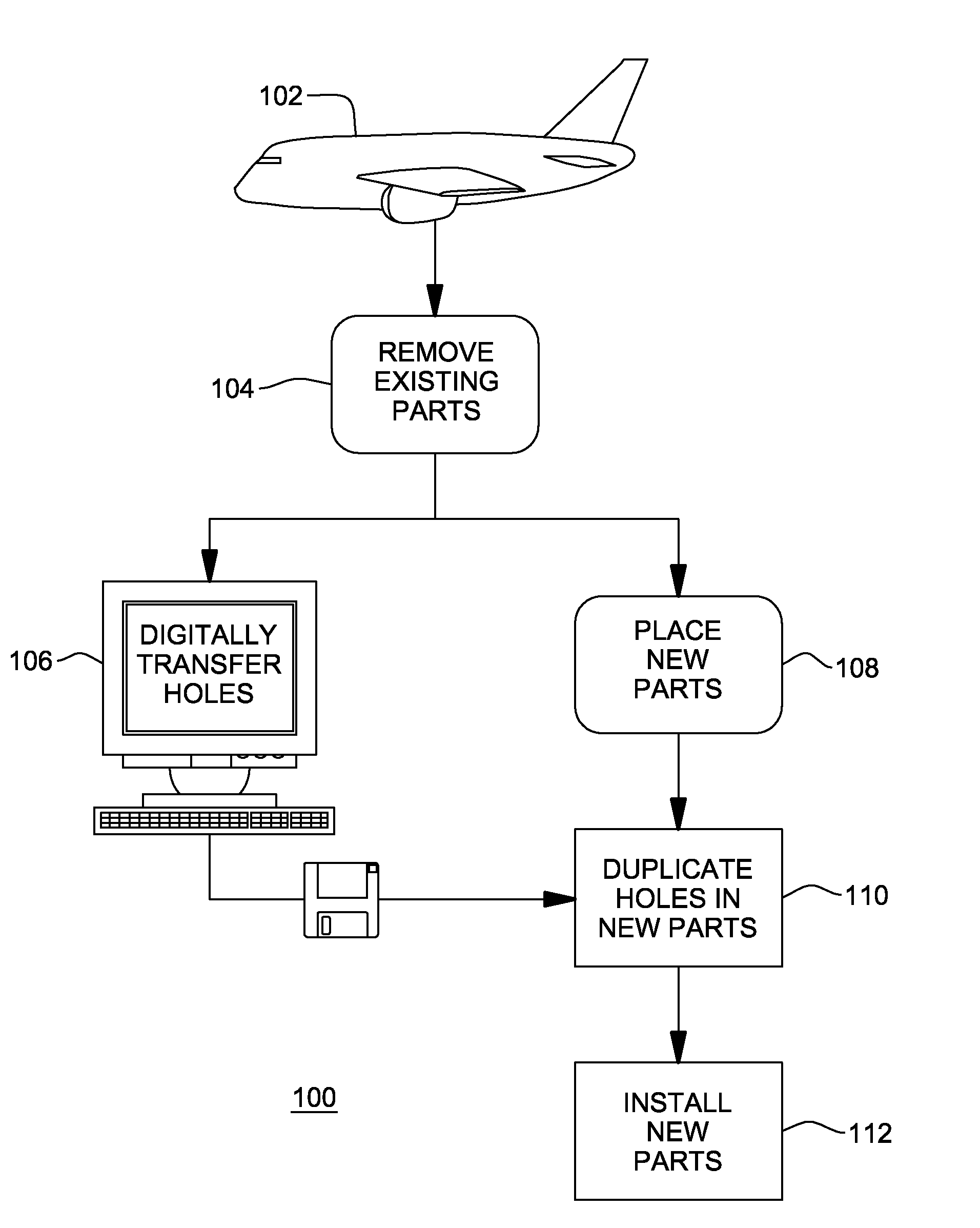
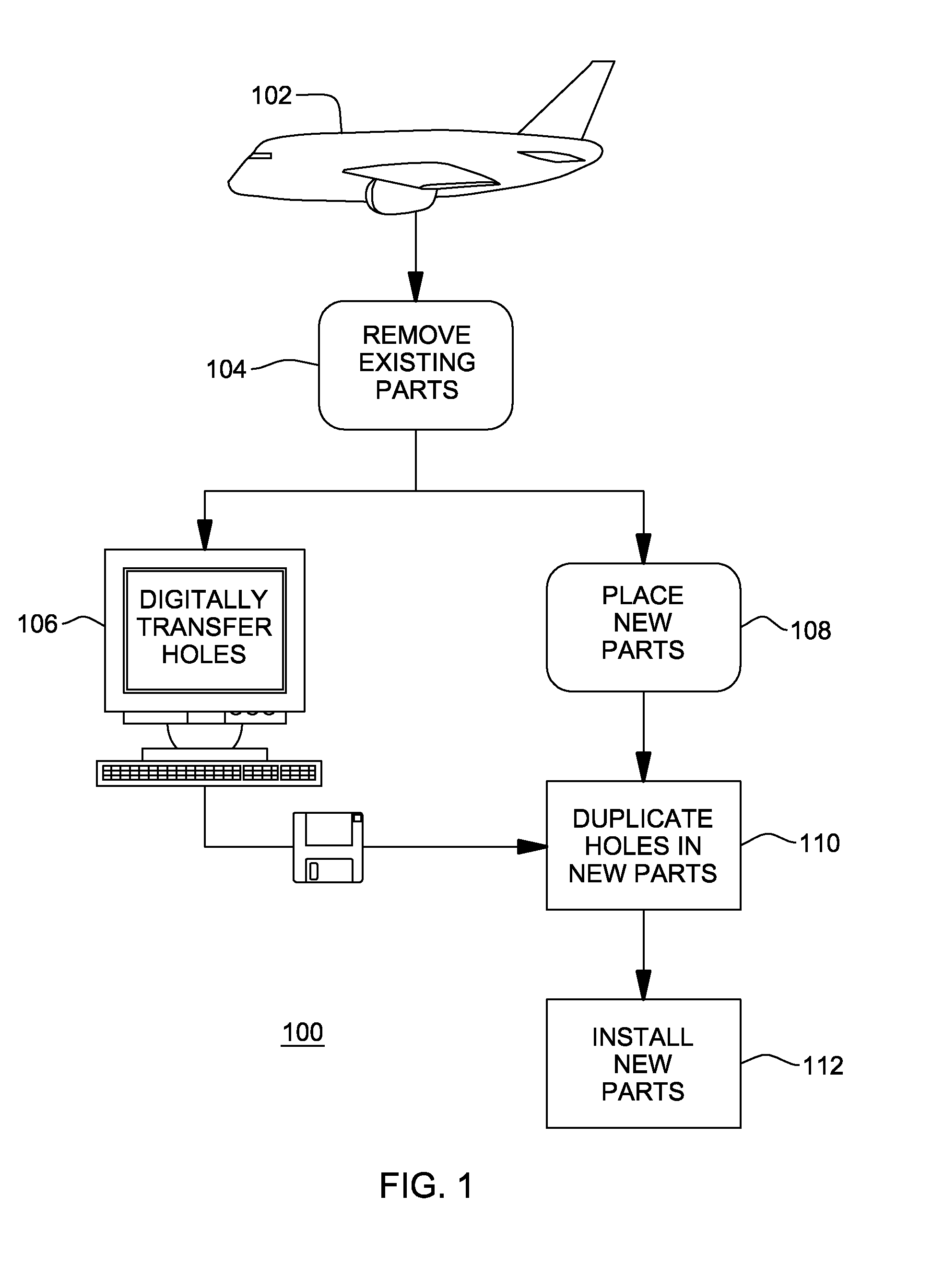
[0016]Turning now to the drawings and more particularly, FIG. 1 shows a flow diagram example 100 of steps in providing replacement parts with precisely located holes that accurately match existing hole locations and sizes according to an advantageous embodiment of the present invention. Existing hole locations and dimensions are gathered, electronically with respective centerlines. The holes are mapped to targets on new replacement parts, projected / printed on the new replacement parts and then, transferred to the replacement parts for efficient field assembly. Since the holes on the replacement parts match holes on the existing part (the part being replaced), replacement is significantly streamlined. Notably, custom fitted replacements exactly match existing parts, even for large applications such as wing skin replacements.

[0017]It should be noted that although the invention is described herein with respect to replacing parts on aircraft, this is for example only and not intended as...


PUM

PropertyMeasurementUnit
photosensitiveaaaaaaaaaa
structureaaaaaaaaaa
hole diametersaaaaaaaaaa

Abstract

A method of replacing an existing part or parts on a structure such as an aircraft. The structure is inducted for modification. An existing part is removed and a new part is temporarily installed. Hole locations are digitally transferred to the new part, e.g., photographically captured in a three-dimensional coordinate measurement system, converted to targets printable in a laser projection system. Targets are laser projected or printed on the replacement part. Holes are drilled at each printed target. The holes drilled at printed targets match hole locations on the existing part. Then, the new/replacement part is permanently attached to the structure.

Description

BACKGROUND OF THE INVENTION[0001]1. Field of the Invention[0002]The present invention generally relates to aircraft maintenance and, more particularly, to providing “as built” hole locations on replacement parts for installation on aircraft.[0003]2. Background Description[0004]Vehicle (e.g., military and commercial aircraft) maintenance and repair may require replacing existing parts. Frequently, existing parts have been modified, e.g., for upgrading or retrofitting the vehicle with state of the art technology. Normally such modification is done individually on a vehicle by vehicle basis, e.g., during scheduled maintenance or routine repair. Also, final assembly or field repairs may have necessitated modifying the existing structure. Thus, the existing parts may vary with some variation of hole patterns and hole diameters from original equipment manufacturer (OEM) parts and, moreover, from vehicle to vehicle. Consequently, it is unlikely that replacement parts are pre-drilled to exa...

Claims


Application Information

Patent Timeline
Patent Type & Authority Applications(United States)
IPC IPC(8): B23P17/00
CPCB64F5/0081G05B19/4207Y10T29/49732G05B2219/31048Y10T29/4973G05B2219/31046B64F5/40Y02P90/02
Inventor PIASSE, MICHAEL L.FARNIOK, CRAIG M.STECKEL, RICHARD J.NOBLES, ORVAL M.
Owner THE BOEING CO
Why Eureka
Try Eureka