
Radio frequency power amplifier and method of assembly thereof

a power amplifier and radio frequency technology, applied in the direction of rf amplifiers, instruments, modifications by conduction heat transfer, etc., can solve the problems of degrading image quality, affecting the and affecting the safety of human body, so as to achieve satisfactory emc performance of rf power amplifiers and effective prevention of rf interferen

Pending Publication Date: 2021-12-02
KONINKLJIJKE PHILIPS NV
View PDF1 Cites 0 Cited by
  • Summary
  • Abstract
  • Description
  • Claims
  • Application Information

AI Technical Summary

Benefits of technology

The present invention provides a radio frequency amplifier assembly with improved electromagnetic interference (EMI) performance. The assembly includes a cooling plate that also serves as a grounding bar, dividing the interior of the assembly into multiple shielded regions that are isolated from each other. The assembly also includes a grounding path and a shielding enclosure for further enhancing EMC performance. The invention has been developed without adding any new components or cost.

Problems solved by technology

Sensitive electronic components impacted by RF and spurious emissions, such as receiving coils, will degrade the image quality.
Furthermore, communication cables and connectors affected by RF and spurious emissions will result in degraded communication between these electronic components.
The most severe issue with poor EMC performance of a RF power amplifier is the safety risk imposed on the human body.
However, EMC performance of existing RF power amplifiers is still not satisfactory for MRI applications.

Method used


Image

  • Radio frequency power amplifier and method of assembly thereof
  • Radio frequency power amplifier and method of assembly thereof
  • Radio frequency power amplifier and method of assembly thereof

Examples


Embodiment Construction

[0034]Like numbered elements in these figures are either equivalent elements or they perform the same function. Elements which have been discussed previously will not necessarily be discussed in later figures if the function is equivalent.

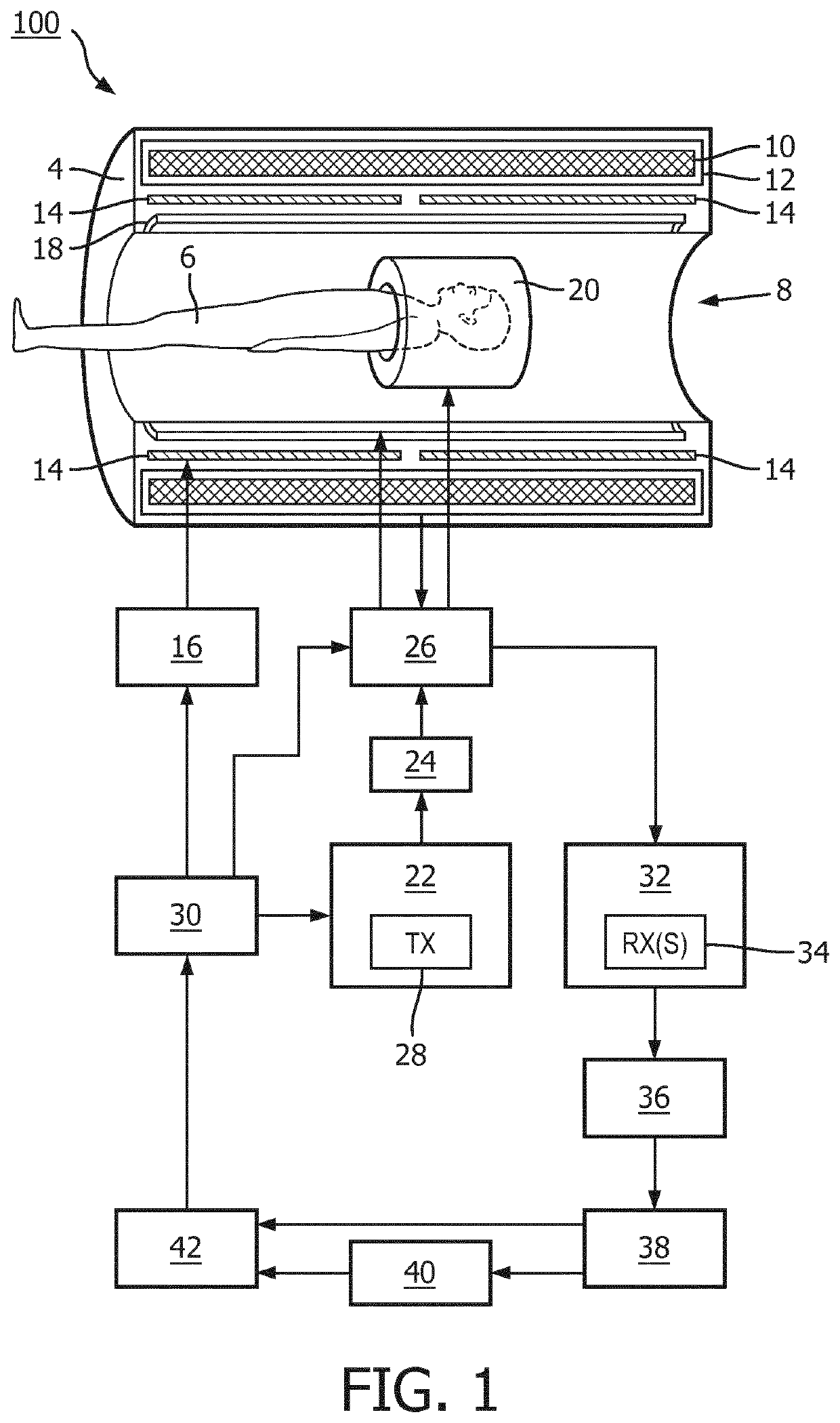
[0035]FIG. 1 illustrates a magnetic resonance imaging (MRI) system 100 that excites nuclei (e.g., associated with isotopes such as IH, 19F, I3C, 31p, etc.) within a subject using a RF power amplifier. The system 100 includes a housing 4. A subject 6 (e.g., a human, an object, etc.) is at least partially disposed within a bore 8 of the housing 4 for one or more MRI procedures (e.g., spin echo, gradient echo, stimulated echo, etc.). A magnet 10 resides in the housing 4. The magnet 10 typically is a persistent superconducting magnet surrounded by a cryo shrouding 12. However, other known magnets (e.g., a resistive magnet, a permanent magnet, etc.) can be employed. The magnet 10 produces a stationary and substantially homogeneous main magnetic field B0...


PUM


Abstract

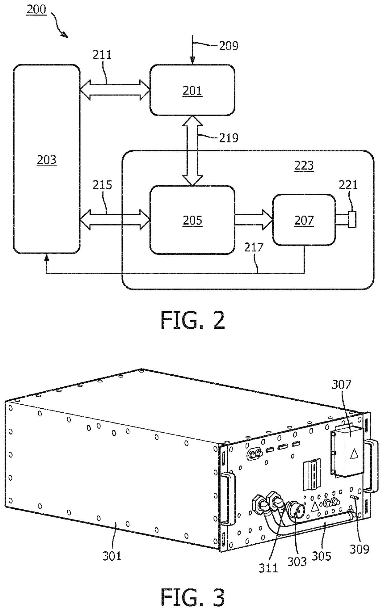
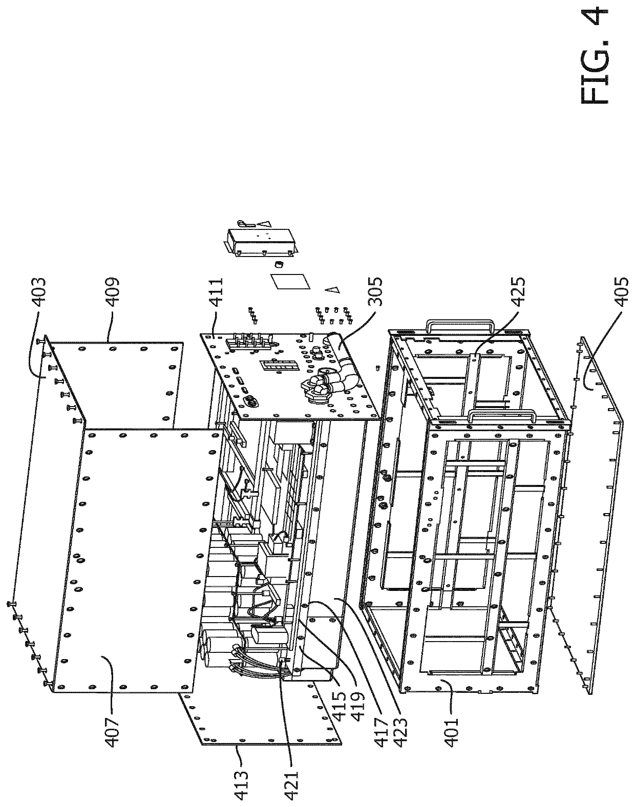
Radio frequency amplifier (200) assembly with effective prevention of RF interference. The radio frequency amplifier comprises an electrically conductive housing (301) that defines an enclosed interior of the radio frequency amplifier assembly, an electrically conductive cooling plate (415) disposed inside the electrically conductive housing and having a first side and an opposite second side, the electrically conductive cooling plate being configured to divide the enclosed interior into a first enclosed region (501) and a second enclosed region (503), and a radio frequency signal processing circuit board (223) equipped with a radio frequency signal processing circuit, the radio frequency signal processing circuit board being positioned in the first enclosed region and disposed on the first side of the electrically conductive cooling plate, and a power supply module and a controller module positioned in the second enclosed region and disposed on the opposite second side of the electrically conductive cooling plate.

Description

FIELD OF THE INVENTION[0001]The invention relates to the field of radio freqency (RF) power amplifiers and more particularly to a RF power amplifier assembly for magentic resonance imaging.BACKGROUND OF THE INVENTION[0002]An RF power amplfier is typically used to convert a low power RF signal into a larger signal of significant power. In the context of a magnetic resonance imaging (MRI) system, the RF power amplifier is connected to RF transmit coils that radiate the RF pulses into the body region to be imaged.[0003]An MRI system is often used for the examination and treatment of patients. By using such a system, the nuclear spins of the body tissue to be examined are aligned by a static main magnetic field B0 and are excited by transverse magnetic fields B1 oscillating in the radiofrequency band. The B1 field is produced by driving electrical currents through specialized RF transmit coils. In nearly all clinical MR imaging applications, the B1 field is transmitted in short 1-5 ms b...

Claims


Application Information

Patent Timeline
Patent Type & Authority Applications(United States)
IPC IPC(8): H03F3/21H03F1/30H05K7/20H05K9/00G01R33/36
CPCH03F3/21H03F1/30H05K7/2039H03F2200/447G01R33/3614H03F2200/451H05K9/0007
Inventor ZENG, KEQIUZHOU, CONGDING, YUANXUZHANG, JUNGYANGMA, JUN
Owner KONINKLJIJKE PHILIPS NV
Learn More