Farrier's tool and method for using

a tool and tool technology, applied in the field offarriers tools and methods, can solve the problems of damage to the horse's feet and legs, lameness of the horse, and damage to the legs of the horse, and achieve the effect of reducing the torque on the bones and ligaments

a tool and tool technology, applied in the field offarriers tools and methods, can solve the problems of damage to the horse's feet and legs, lameness of the horse, and damage to the legs of the horse, and achieve the effect of reducing the torque on the bones and ligaments

US20080289199A1Inactive Publication Date: 2008-11-27HEALEY PETE

Image

  • Farrier's tool and method for using
  • Farrier's tool and method for using

Examples


Embodiment Construction

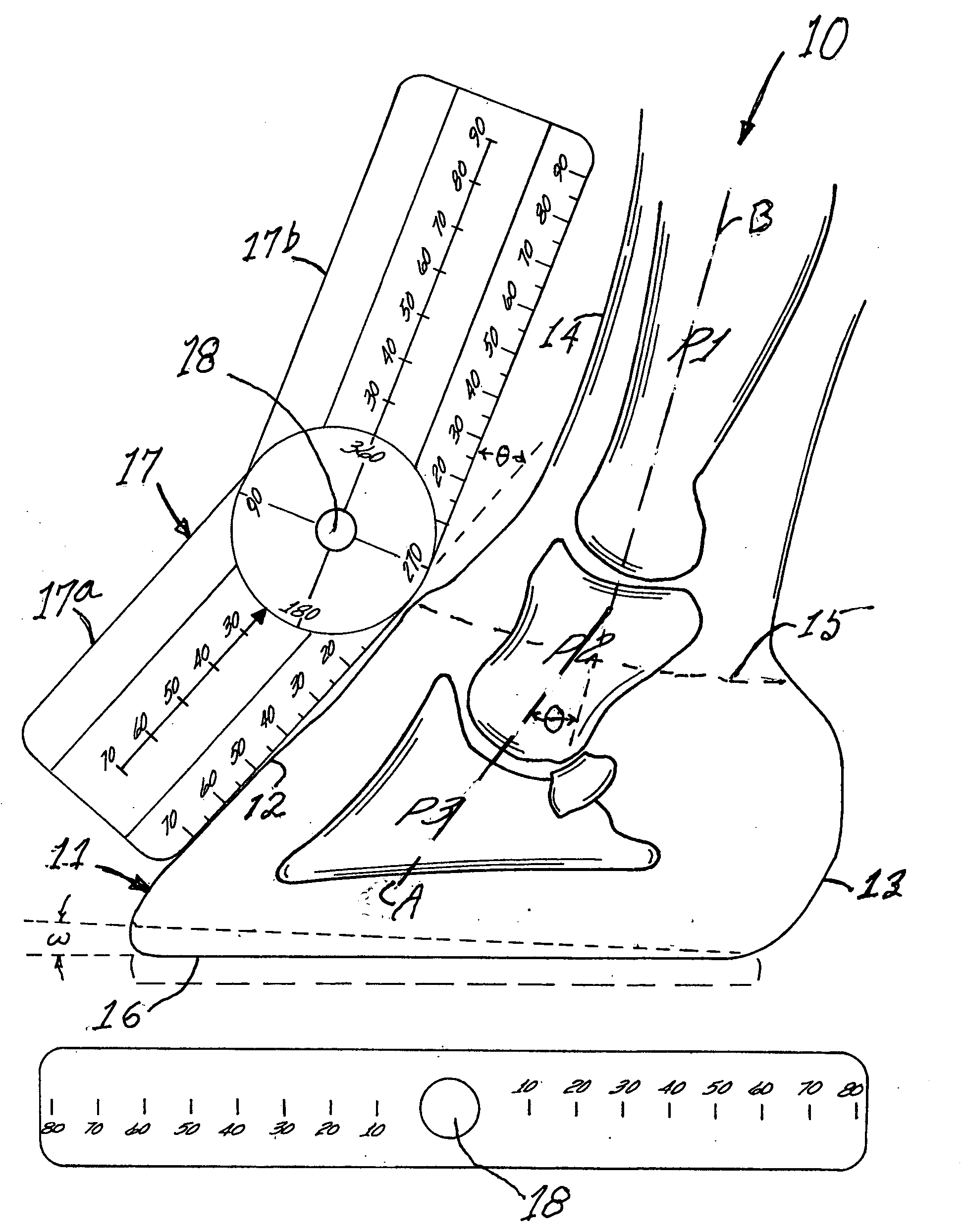
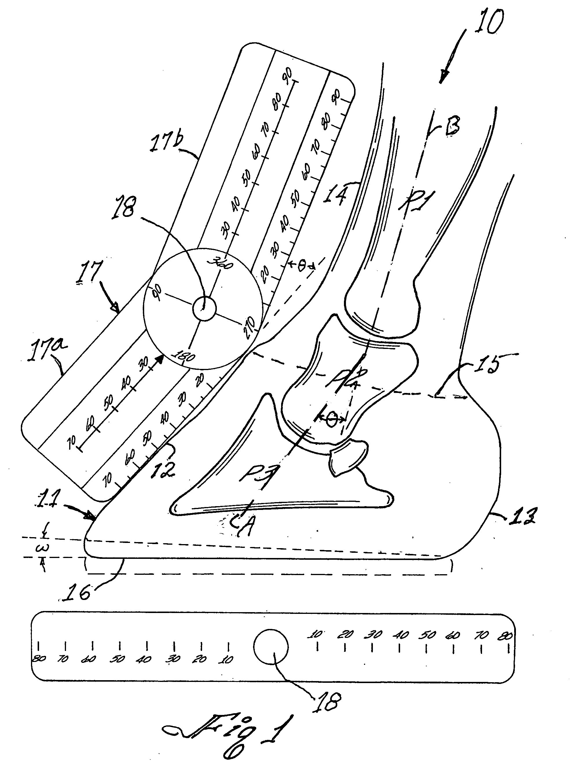
[0012]Turning now to FIG. 1, the anatomy of the foot 10 of an unshod horse is shown in longitudinal cross-sectional view. The hoof 11 has an anterior or forward edge 12 and a heelbulb 13 on the rearward edge. The junction between the upper surface of the hoof 11 and the skin 14 is the coronet band 15. In addition to the bottom surface 16 of the hoof 11 being flat, the contour of the anterior (or forward) portion 16 of the hoof 12 is also important. When a horse lifts its hoof to walk, the heel leaves the ground first, temporarily transferring weight disproportionately to the anterior or forward edge 16 of the hoof. The rising foot rotates around a transverse axis in the foot which is called the break-over axis. If the lower surface of the forward portion of the hoof (or shoe) is flat, the weight transferred thereto creates a high torque which forces the hoofwall away from the coffin bone P3 which can result in damage thereto. In U.S. Pat. No. 7,165,623, the content of which is incor...


PUM


Abstract

A farrier's tool and a method of using the tool for preparing the hoof of a horse to receive a shoe. The tool is, in one aspect, a goniometer used for determining the angle of heel-toe taper when preparing a horse's hoof to receive a shoe. After the angle between the anterior surface of the first phalanx of the foot and the anterior surface of the hoof is determined, the ground-facing surface of the hoof is beveled by means of a trimming tool at an angle determined by the goniometer to reduce uneven pressure on the underlying coffin bone and to balance the tension on the tendons and ligaments in the horse's foot, particularly during locomotion. The method provides, inter alia, means for accurately aligning the hoof capsule with the coffin bone in the hoof.

Description

BACKGROUND OF THE INVENTION[0001]1. Field of the Invention[0002]The present invention relates generally to a farrier's tool and a method for preparing the hoof of a horse for receiving a shoe, and more particularly, to a measuring tool operable for determining the optimal angle of the plane of the ground-facing surface of the hoof with respect to the alignment of bones in the horse's foot, the angle thus determined enabling the farrier to properly bevel the horse's hoof in preparation for receiving a shoe.[0003]2. Prior Art[0004]Horses need periodic shoeing to protect their hooves and prevent damage to their feet. Typically, the wear and tear on the shoe and the normal growth and expansion of the hoof requires filing, trimming and reshoeing every six to eight weeks. In accordance with the prior art, prior to installing a horseshoe, the farrier first removes the old shoe then determines the flatness and the plane of the bottom, ground-contacting portion of the hoof (i.e., the solar s...

Claims


Application Information

Patent Timeline
27 Nov 2008
Publication
US20080289199A1
IPC
A01L11/00; B43L7/10
CPC
A01L11/00; G01B3/56
Inventors
HEALEY, PETE