
Filtering System for the Air Directed Towards an Internal Combustion Engine Intake

a filtering system and air technology, applied in the direction of combustion-air/fuel-air treatment, filtration separation, separation processes, etc., can solve the problems of clogging of the filter baffle more or less rapidly, affecting the performance of the engine, and requiring regular maintenan

Inactive Publication Date: 2008-11-27
UFI FILTERS SPA
View PDF8 Cites 73 Cited by
  • Summary
  • Abstract
  • Description
  • Claims
  • Application Information

AI Technical Summary

Benefits of technology

[0015]The object of the present invention is to overcome the said drawback within the framework of a simple, rational and low-cost solution.
[0019]By virtue of this solution, the overall size of the filtering system is reduced substantially, to become that of the second filtering baffle, which can be constructed to operate effectively for the entire useful life of the relative engine, and can hence be located in any position within the engine compartment.
[0021]For this reason, in a preferred embodiment of the invention said first filtering baffle is flexible, enabling it to be adapted to any sinuous development of the air feed conduit.

Problems solved by technology

The air withdrawn from the environment is known to contain solid particles in suspension having sufficiently large dimensions to seriously damage the engine if these reach the cylinder interiors.
During use, this filtering baffle clogs more or less rapidly, and hence requires regular maintenance with periodic replacement.
For these reasons, the filtering baffle and relative filter box have to be located in an easily accessible position of the engine compartment, thus placing a substantial limit on the distribution of the spaces available within the engine compartment itself.
A drawback of these filtering systems provided with a double filtering baffle is that the first filtering baffle, together with its containing box, is still of large size and must be located in an easily accessible position of the engine compartment, to be periodically replaced.
This size, although less than a single filtering baffle, likewise places a limitation on space distribution within the engine compartment, which is more substantial the smaller the overall available volume.

Method used


Image

  • Filtering System for the Air Directed Towards an Internal Combustion Engine Intake
  • Filtering System for the Air Directed Towards an Internal Combustion Engine Intake
  • Filtering System for the Air Directed Towards an Internal Combustion Engine Intake

Examples


Embodiment Construction

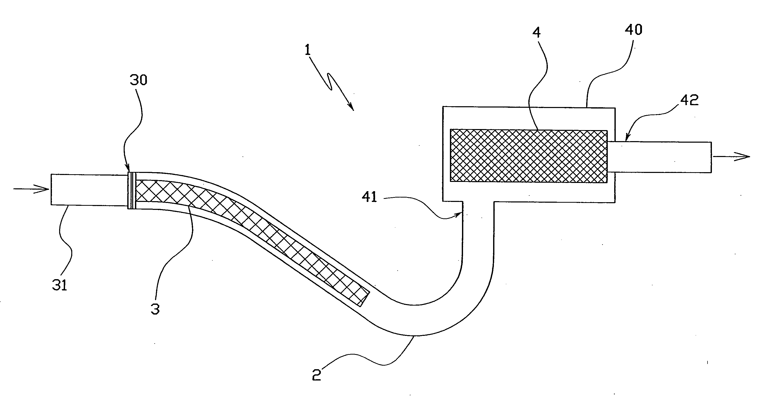
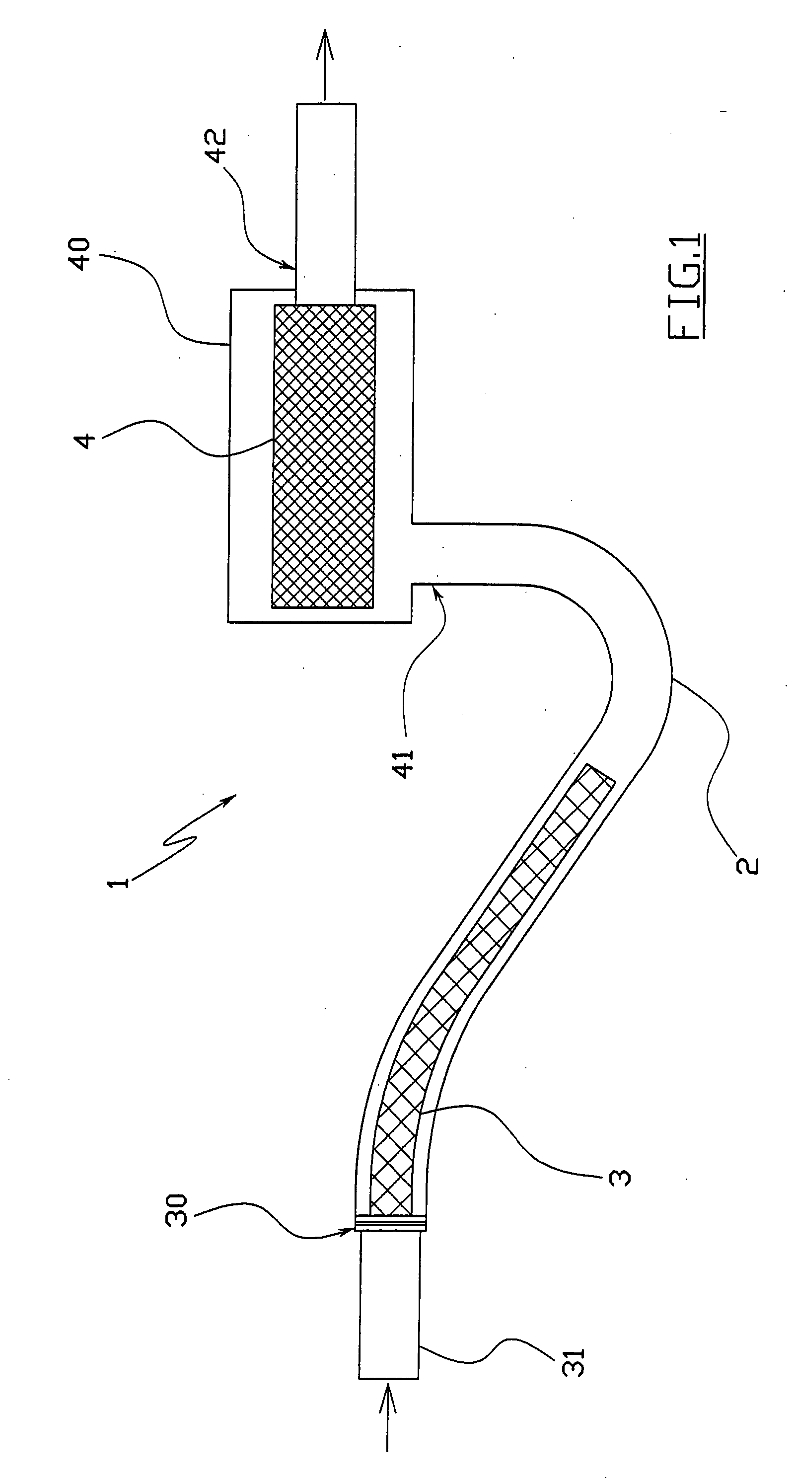
[0029]The filtering system 1 of the present invention is provided for filtering the air directed towards the intake of an automotive internal combustion engine.

[0030]Said filtering system 1 is located in the interior of the engine compartment of the vehicle with which the engine is associated, to treat the air withdrawn from the external environment.

[0031]This air enters through one or more air intake ports which open within the vehicle body, then flows through the filtering system 1, to finally pass into an intake manifold, which is connected to the engine cylinders via the intake valves.

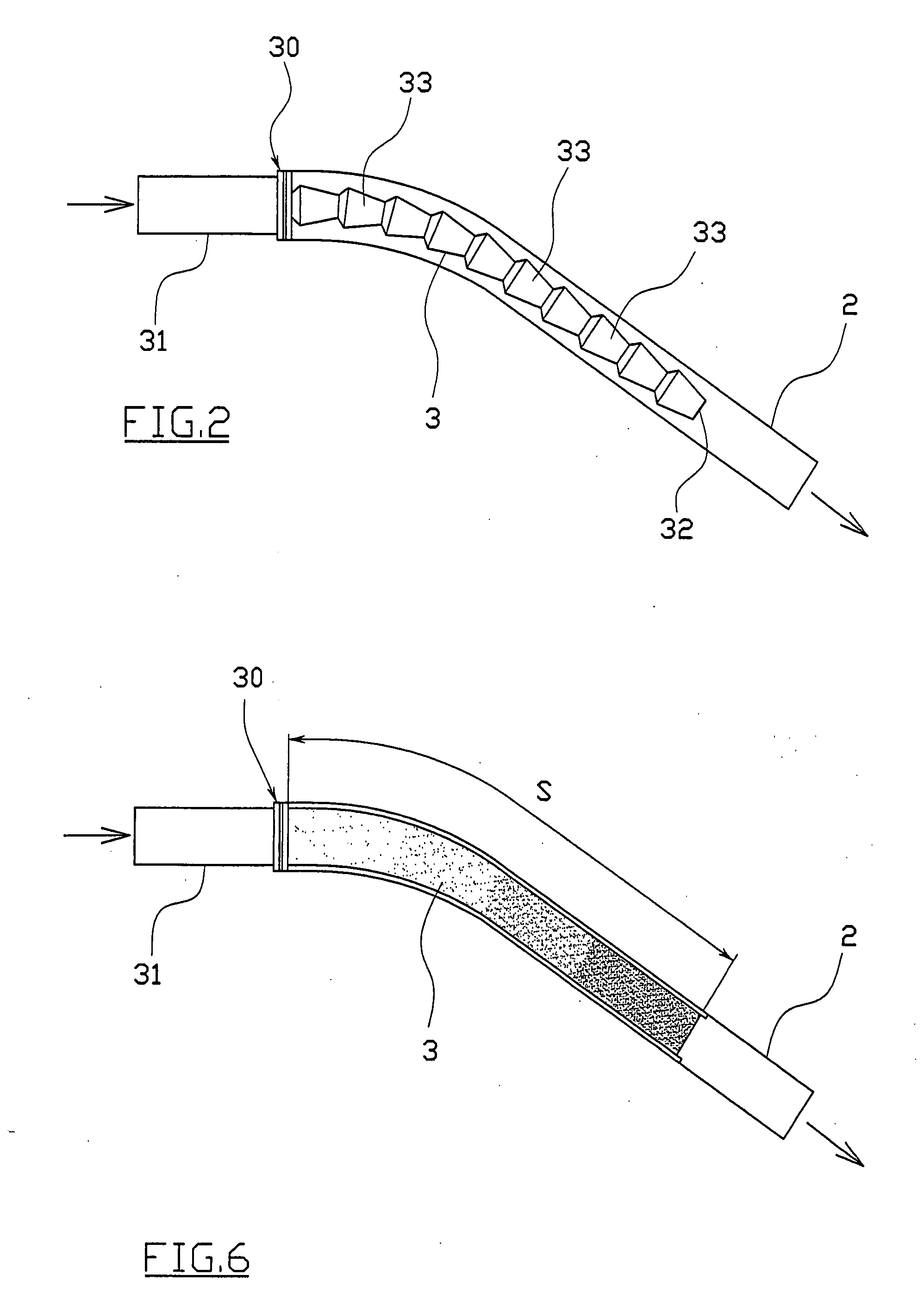
[0032]As shown in FIG. 1, the filtering system 1 comprises a feed conduit 2 of constant cross-section with a diameter generally between 70 and 90 millimetres, which conveys the air through two separate series-disposed filtering baffles, namely a first baffle 3 and a second baffle 4.

[0033]Said first and second filtering baffle 3 and 4 are provided to retain the solid particles carried in suspension ...


PUM

PropertyMeasurementUnit
Pore sizeaaaaaaaaaa
Pore sizeaaaaaaaaaa
Flexibilityaaaaaaaaaa

Abstract

A filtering system for the air directed towards an internal combustion engine intake, comprising a feed conduit (2) conveying the air through two separate series-disposed filtering baffles (3, 4), of which a first filtering baffle (3) retains the large-dimension solid particles carried in suspension by said air, and a second filtering baffle (4) retains the smaller-dimension solid particles which have been allowed to pass by the first filtering baffle (3); said first filtering baffle (3) being of generally elongated shape and being inserted directly into said air feed conduit (2).

Description

TECHNICAL FIELD[0001]The present invention relates to a filtering system for the air directed towards an internal combustion engine intake. More particularly, the present invention relates to a filtering system associated with an automotive internal combustion engine, to be located within the engine compartment of the vehicle on which the engine is installed.PRIOR ART[0002]To operate diesel or petrol internal combustion engines, their cylinders must be fed with a certain air quantity withdrawn from the surrounding environment, to provide the necessary oxygen for fuel combustion.[0003]This air is generally withdrawn through one or more air intake ports opening in the vehicle body, and is then conveyed towards an intake manifold which communicates directly with the engine cylinders via the intake valves.[0004]The air withdrawn from the environment is known to contain solid particles in suspension having sufficiently large dimensions to seriously damage the engine if these reach the cy...

Claims


Application Information

Patent Timeline
IPC IPC(8): B01D24/24B01D46/52
CPCB01D46/0012B01D46/2403B01D46/521B01D50/002B01D2265/06B01D2275/201B01D2279/60F02M35/02483B01D50/20
Inventor GIRONDI, GIORGIO
Owner UFI FILTERS SPA
Features
  • Generate Ideas
  • Intellectual Property
  • Life Sciences
  • Materials
  • Tech Scout
  • Unparalleled Data Quality
  • Higher Quality Content
  • 60% Fewer Hallucinations
Learn More