Methods and Apparatus for Power Generation

Inactive Publication Date: 2008-11-27
RENEWABLE ENERGY SYST LTD
View PDF17 Cites 72 Cited by
  • Summary
  • Abstract
  • Description
  • Claims
  • Application Information

AI Technical Summary

Benefits of technology

[0005]It is an object of a preferred embodiment of the present invention to provide a method and/or an apparatus for power gen

Problems solved by technology

However, in recent times energy availability has d

Method used


Image

  • Methods and Apparatus for Power Generation
  • Methods and Apparatus for Power Generation
  • Methods and Apparatus for Power Generation

Examples


Embodiment Construction

[0070]The term “fluid” is used here in to denote a liquid, gas, or a mixture of liquid and gas.

[0071]The term “working fluid” is used herein to denote any fluid suitable for use with the associated working fluid circuit, whether in a liquid or gaseous state.

[0072]The term “heat pump” is used to describe apparatus which are capable of transferring heat from a first medium to a relatively warmer a second medium, for example a phase change heat pump. The term includes embodiments in which heat is, in practice, transferred from a higher temperature medium to a lower temperature medium.

[0073]The term “turbine” is used to describe a turbomachine which converts energy from a working fluid vapour to useful power. Where the context requires it, the term “turbine” includes devices which incorporate means to generate electrical power.

[0074]The terms “upstream” and “downstream” are used to indicate a direction relative to the normal flow of working fluid.

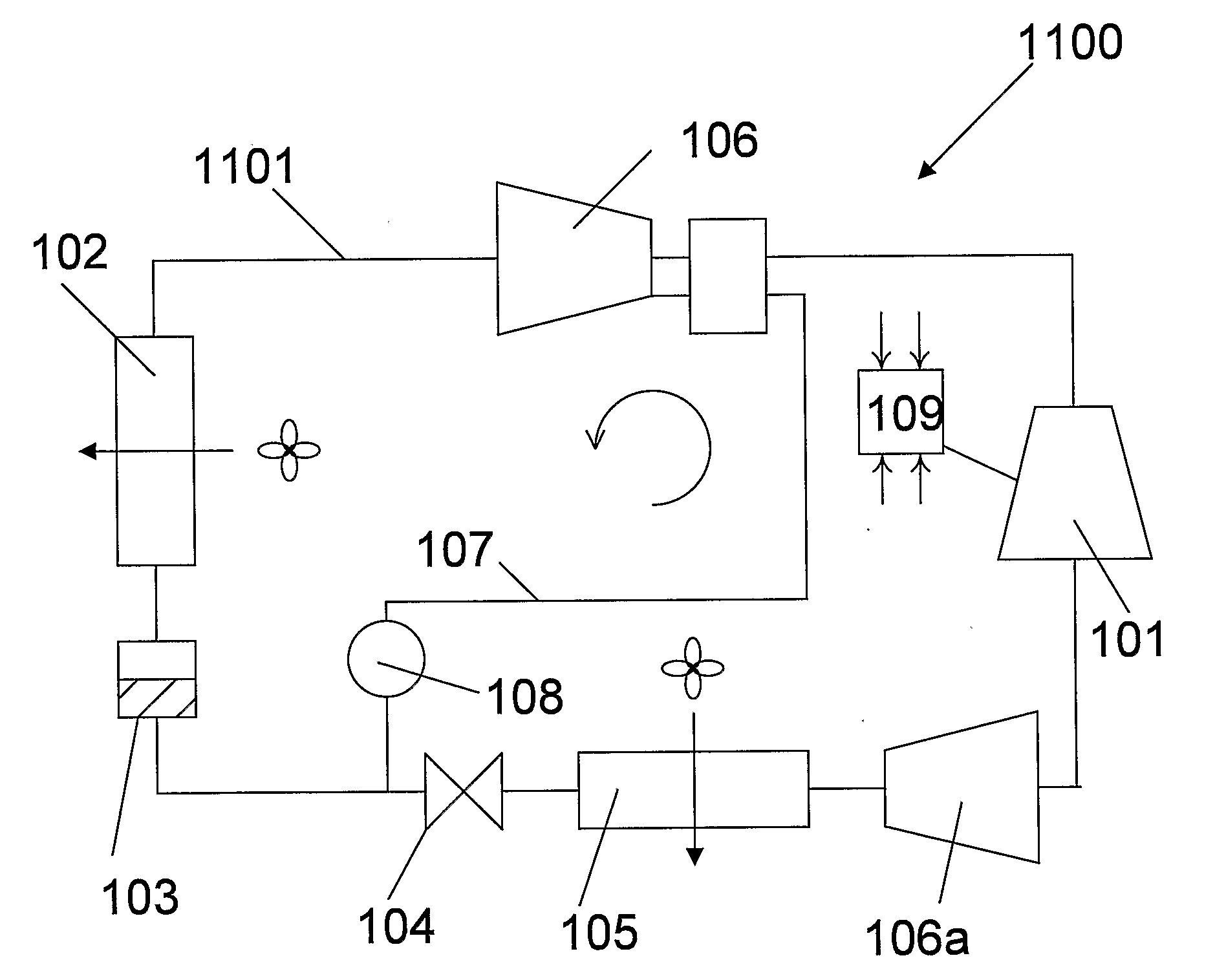
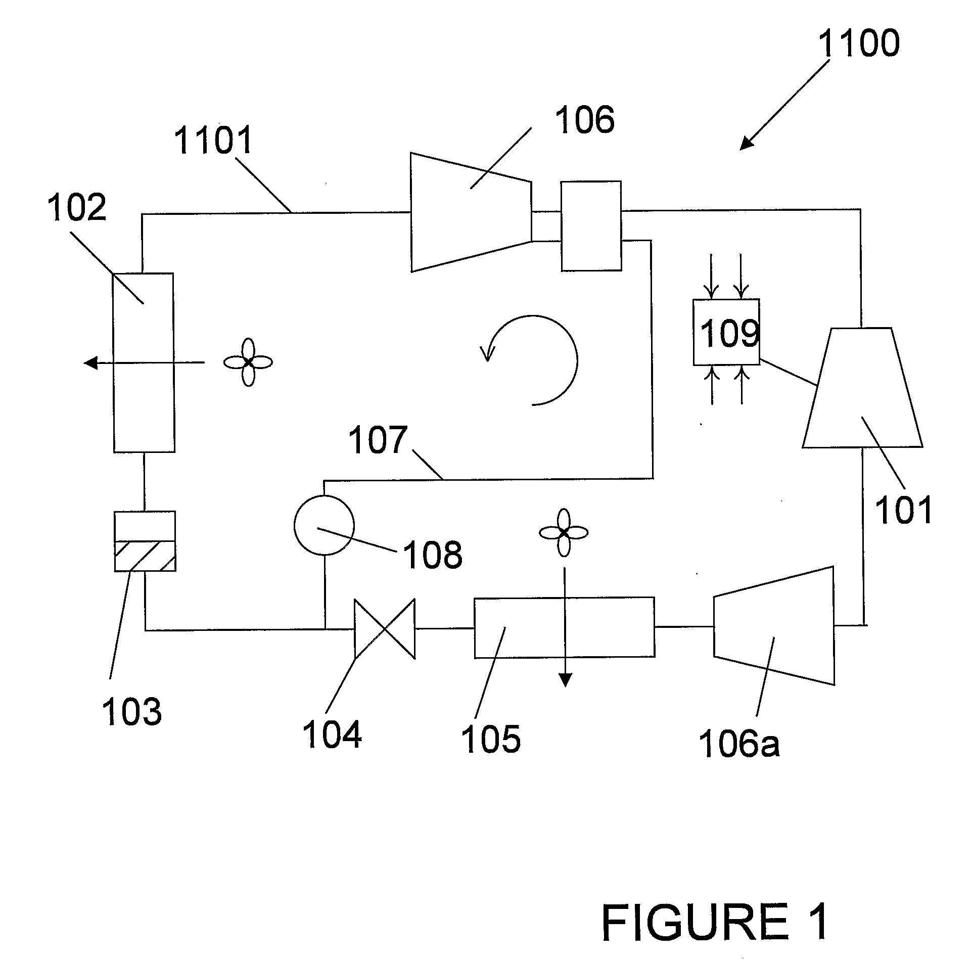
[0075]Referring first to FIG. 1, a heat ...


PUM


Abstract

A refrigeration apparatus (7200) includes a heat pump circuit (7201) and a power generation circuit (7100). The power generation circuit (7100) includes an evaporator (701) including a first and a second heat exchanger (710a, 710b), a turbine (702), a condenser (703) and a pump (704). The first heat exchanger (710a) absorbs heat rejected from the heat pump circuit (7201) into a power generation circuit (7100) while the second heat exchanger (710b) further heats the fluid. The power generation circuit (7100) includes a bypass (707) which allows a portion of working liquid to enter the turbine (702) without passing through the evaporator (701). A heat pump (704) with similar bypass is also disclosed. Also disclosed are dual stage turbine design and a nozzle (10300) for a turbine which includes two fluid paths (1011, 1014) that adapted to receive and mix the liquid and vapour streams of working fluid, so that the liquid working fluid is vaporized by the heat from the vapour working fluid.

Description

FIELD OF THE INVENTION[0001]The present invention relates to methods and apparatus for utilizing heat which would otherwise be rejected to the environment, and in particular, but not exclusively to methods and apparatus for generating power from a Rankine type cycle and / or at least reducing the net power consumed by a heat pump apparatus.BACKGROUND TO THE INVENTION[0002]It is well known that almost every practical thermodynamic system rejects some heat to the environment. In times of cheap energy production this has not been viewed as a problem. However, in recent times energy availability has dwindled, and the cost of energy has begun to rise. Accordingly, a need has been recognized around the world to ensure that any energy consumed is used as efficiently as possible.[0003]Two well known examples of systems which reject a relatively high proportion of the energy they consume as heat are refrigeration cycles and Rankine cycles.[0004]It would be beneficial to develop systems and met...

Claims


Application Information

Patent Timeline
IPC IPC(8): F01K25/06
CPCF01D15/005F01K21/005F02C1/002F02C1/007F25B11/02F25B29/003F25B2339/047F25B2400/14F28C3/08H02K7/1823H02M7/10F05D2210/13
Inventor DRYSDALE, KENNETH WILLIAM PATTERSON
Owner RENEWABLE ENERGY SYST LTD
Why Eureka
Try Eureka