Four wheeled utility vehicle

a utility vehicle and four-wheel technology, applied in vehicle components, propulsion units, propulsion parts, etc., can solve the problems of high temperature of the engine room, difficult to efficiently utilize the air taken from the opening in the right and left side walls, etc., and achieve the effect of efficient introduction of cooling air

Inactive Publication Date: 2008-11-27
KAWASAKI HEAVY IND LTD
View PDF4 Cites 44 Cited by
  • Summary
  • Abstract
  • Description
  • Claims
  • Application Information

AI Technical Summary

Benefits of technology

[0009]The present invention addresses the above condition, and an object of the present invention is to provide a

Problems solved by technology

Further, in the case of mounting a high-power engine, it is hard to sufficiently cool only by the air taken from under the vehicle body, therefore the engine room 103 becomes high temperature.
Further, even if the cooling structure in which the opening is formed in the side wall of the engine room of the truck is applied to the engine room of the four wheeled utility vehicle, it is so hard to effi

Method used


Image

  • Four wheeled utility vehicle
  • Four wheeled utility vehicle
  • Four wheeled utility vehicle

Examples


Embodiment Construction

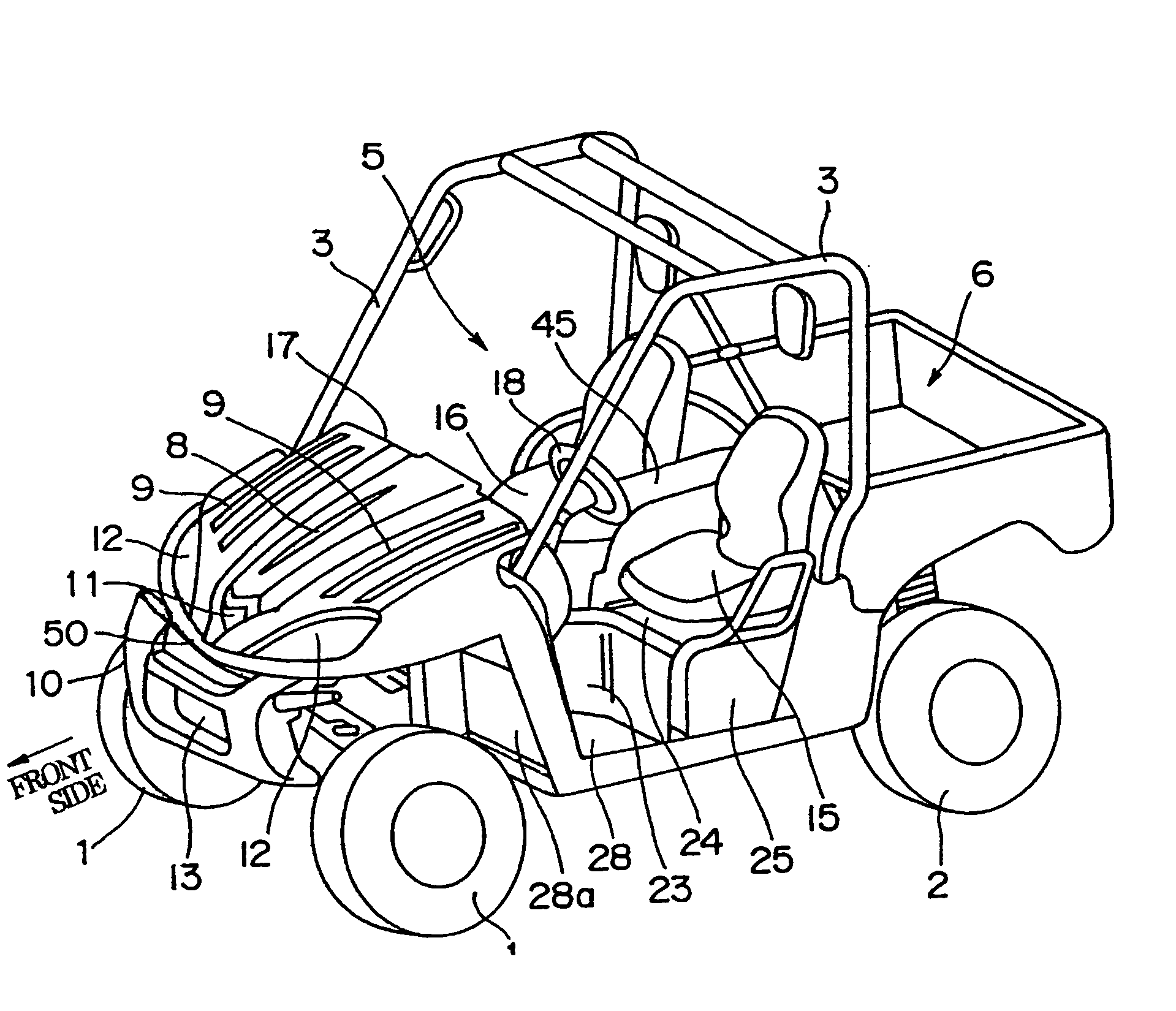
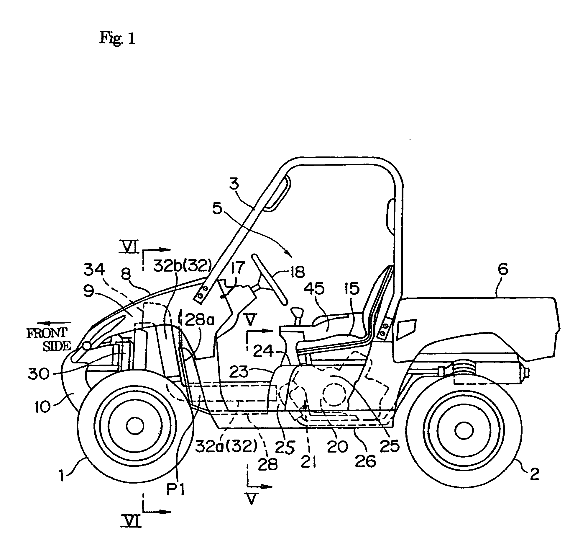
[0029]FIGS. 1 to 6 show an embodiment of a four wheeled utility vehicle in accordance with the present invention. A description will be given of the present invention with reference to these drawings. In this case, in a concept of directions used for the following description, a front side as seen from a rider riding on the vehicle shown in FIG. 1, that is, a direction in which the vehicle moves forward is called a front side of the vehicle and each of constituting elements of the vehicle, except as otherwise specified.

[Whole Structure of Four Wheeled Utility Vehicle]

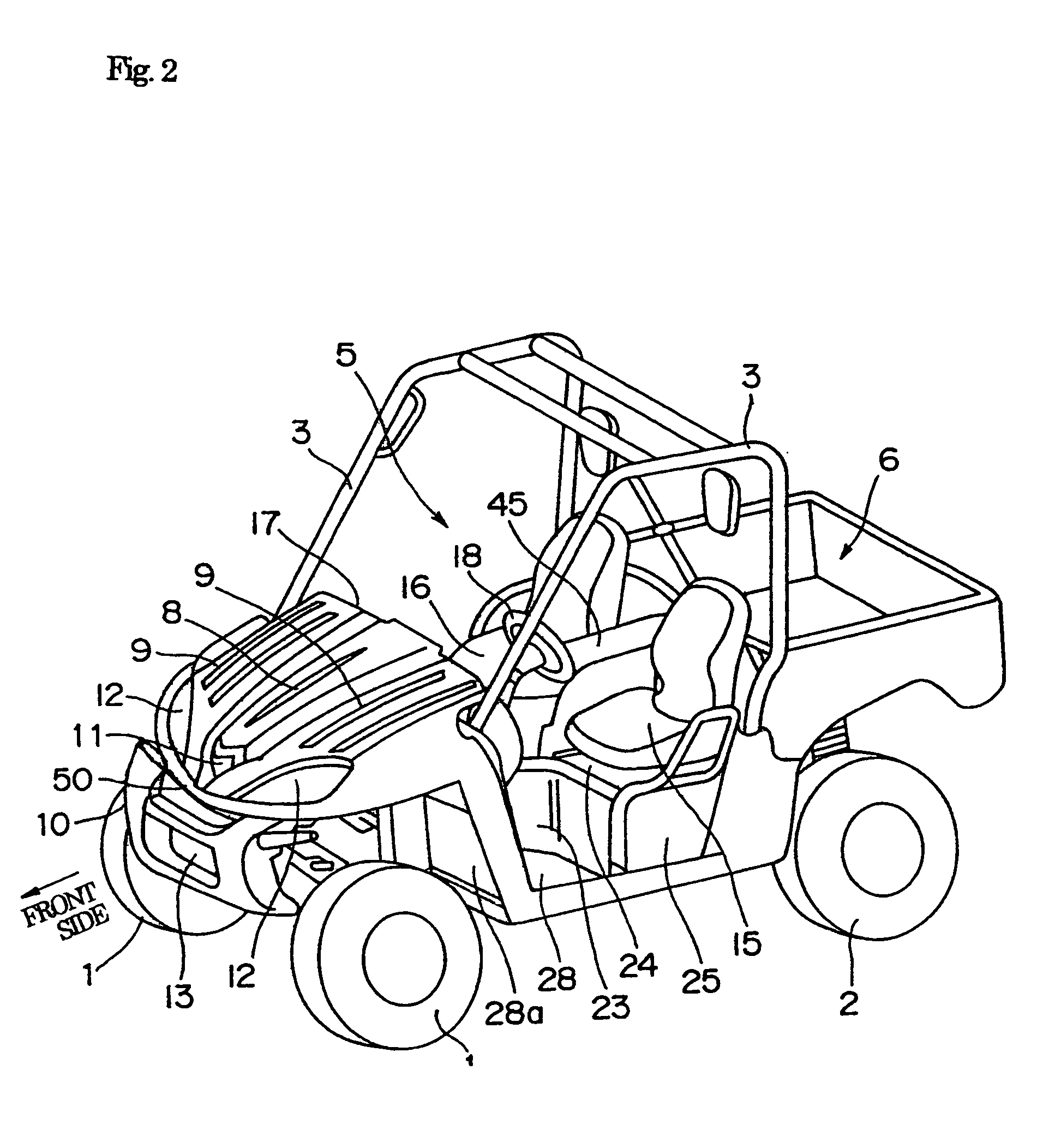
[0030]FIG. 2 is a simplified perspective view of the four wheeled utility vehicle. A pair of right and left front wheels 1 are provided in a front portion of the vehicle, a pair of right and left rear wheels 2 are provided in a rear portion of the vehicle, a cabin 5 surrounded by a protecting frame 3 is provided between the front wheels 1 and the rear wheels 2, and a back carrier 6 is provided behind the cabin 5. Furthe...


PUM


Abstract

The invention provides a four wheeled utility vehicle which can efficiently introduce a cooling air into an engine room from a front side of the vehicle. The vehicle is provided with a cabin arranged between front wheels and rear wheels and accommodating a seat of the vehicle and an operating portion in front of the seat to steer the vehicle; an engine room arranged within the cabin or at a position rearward of the cabin to accommodate an engine of the vehicle therein, and configured to be covered by a wall surface at least in a front side and an upper side of the engine; an air duct extending forward from the engine room, and introducing an engine room cooling air into the engine room.

Description

BACKGROUND OF THE INVENTION[0001]1. Field of the Invention[0002]The present invention relates to a four wheeled utility vehicle, particularly, relates to an engine room cooling structure thereof.[0003]2. Description of the Related Art[0004]FIG. 8 shows an example of a conventional four wheeled utility vehicle. The vehicle includes a cabin 110 which is provided between a pair of right and left front wheels 101 and a pair of right and left rear wheels 102, an engine room 103 arranged under a seat 104 in the cabin 110, and an engine 105 accommodated in the engine room 103. The engine room 103 is generally surrounded by a front wall 111 covering a front side of the engine 105, an upper wall 112 covering an upper side of the engine 105, and an under guard 106 covering a bottom side of the engine 105. In this case, since the engine room 103 in FIG. 8 is shown by a cross section, side walls of the engine room 103 is not illustrated, however, right and left sides of the engine room 103 are ...

Claims


Application Information

Patent Timeline
IPC IPC(8): B62D21/00
CPCB60K11/06B60K13/02
Inventor KOSUGE, HIDEYOSHIOKI, TOSHINORI
Owner KAWASAKI HEAVY IND LTD
Why Eureka
Try Eureka