Wheel Suspension

a technology of individual wheel and suspension, which is applied in the direction of pivoted suspension arms, transportation and packaging, trucks, etc., can solve the problems of the choice of engine placement, limiting the possible ground clearance, and generally difficult installation of solutions, etc., to achieve low weight, reduce the effect of spring travel and low engine placemen

Inactive Publication Date: 2008-11-27
VOLVO LASTVAGNAR AB
View PDF25 Cites 28 Cited by
  • Summary
  • Abstract
  • Description
  • Claims
  • Application Information

AI Technical Summary

Benefits of technology

[0007]The solution according to the invention produces an improved wheel suspension which combines low weight, relatively long spring travel and a built-in stabilizer. The invention also allows a low engine placement in order to obtain a low centre of gravity.

Problems solved by technology

Such solutions are generally difficult to install owing to the limited space which is available.
This is especially problematic for front wheel suspensions, in which the space is severely limited by the placement of the engine between the longitudinal frames.
A further problem with current wheel suspensions is that they limit the possible ground clearance and the choice of engine placement.
These requirements are difficult to combine with current solutions, which comprise spring-mounted, rigid-axles extending beneath the frame and the engine.
The drawbacks with this solution are that it is complicated, owing to all the extra rods needed to absorb forces in the longitudinal direction and to transmit steering motions, and owing to the fact that the auxiliary frame requires a lot of space.
This solution is not, however, applicable to steerable front wheel suspensions and cannot absorb any substantial forces in the lateral direction.

Method used


Image

  • Wheel Suspension
  • Wheel Suspension
  • Wheel Suspension

Examples


Embodiment Construction

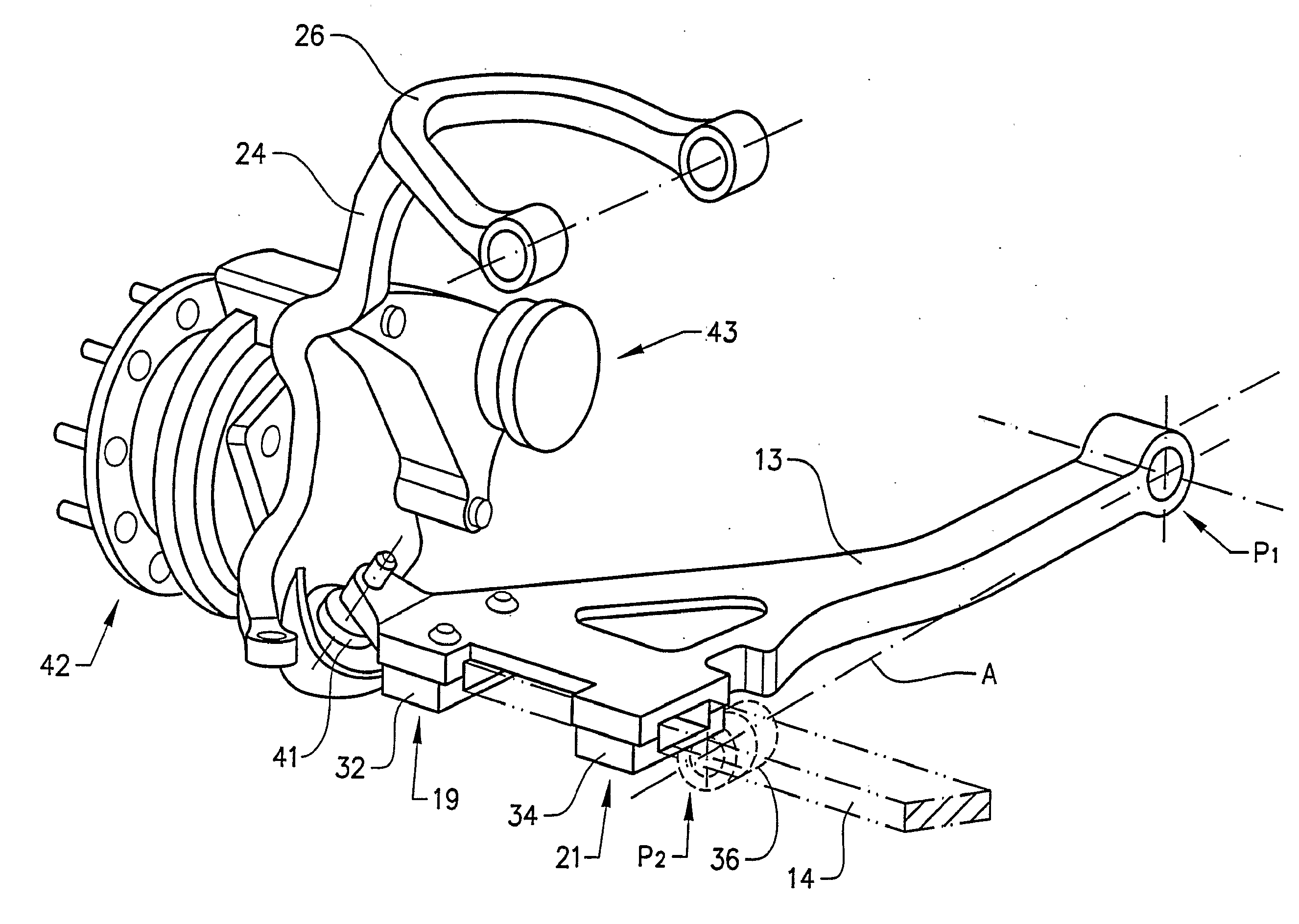
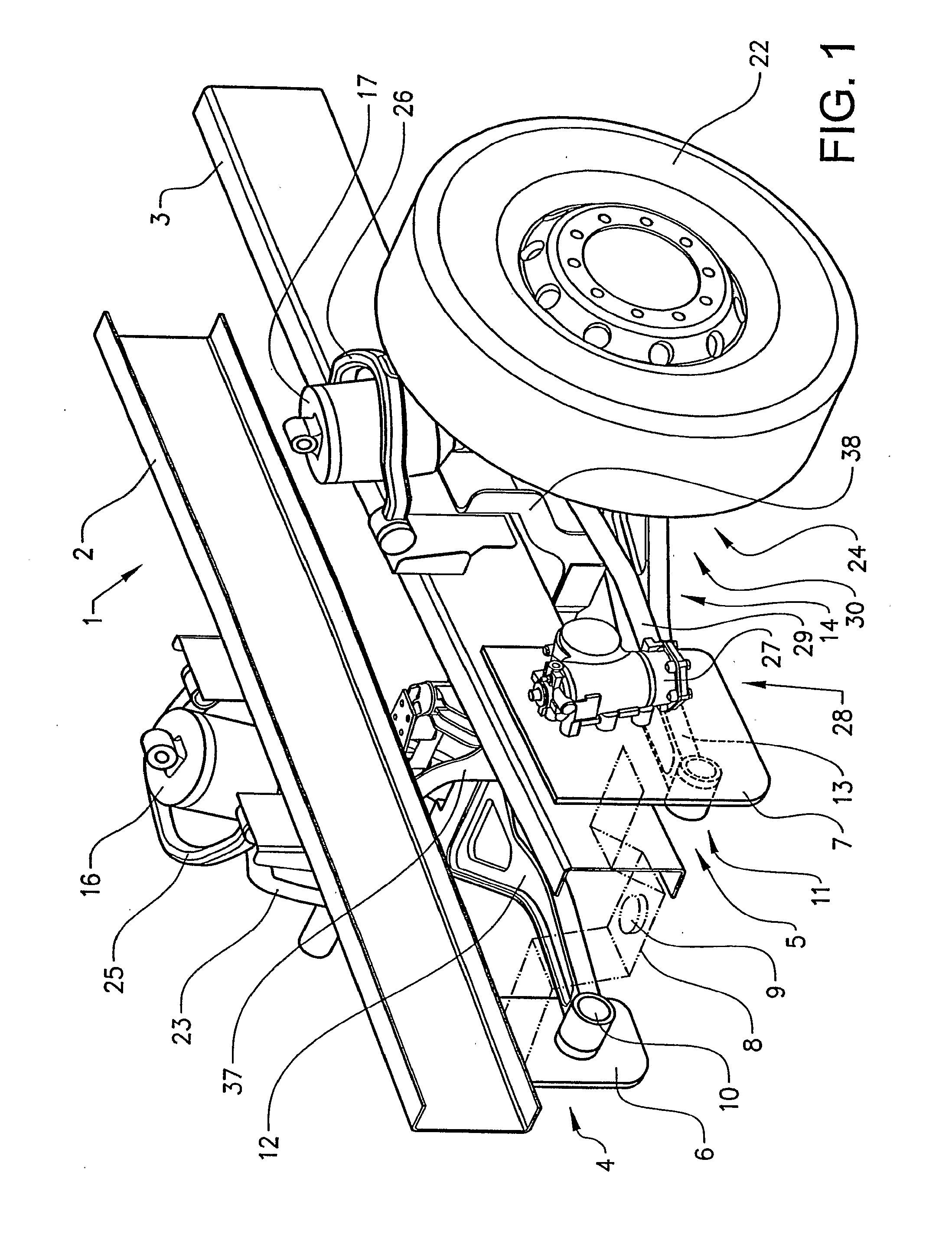
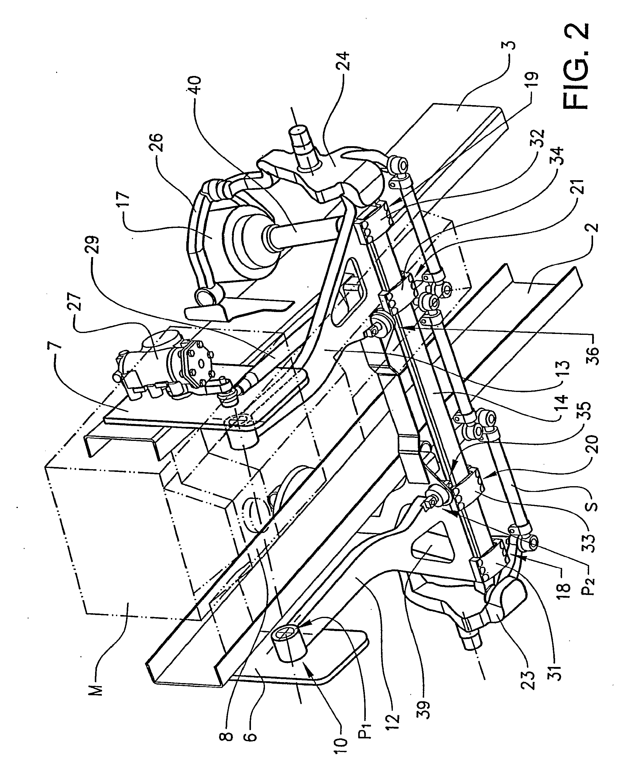
[0023]The preferred embodiments, which will be described with reference to the figures of the drawing, are intended to be applied to a vehicle frame in the form of two longitudinal U-beams or I-beams, in which the engine is mounted between the beams. In the following text, the construction of the individual wheel suspension for one side of the vehicle is described, unless otherwise specified.

[0024]FIGS. 1 and 2 show a front wheel suspension according to the invention viewed in perspective view obliquely from the front and above, and obliquely from the front and below, respectively. The front wheel suspension in this example is intended for a vehicle built on a frame 1 consisting of a pair of longitudinal beams 2, 3. In their front parts, the beams have a pair of brackets 4, 5, which comprise a plate 6, 7 extending down beneath the bottom face of the frame beams. These plates 6, 7 constitute attachments for a transverse beam 8 connecting the longitudinal beams 2, 3. The transverse be...


PUM


Abstract

A wheel suspension for the suspension of a wheel in a motor vehicle includes a wheel spindle connected to a steering knuckle holder, a link arm connecting the steering knuckle holder to the vehicle, and a stabilizer fastened transversely to the longitudinal axis of the vehicle. The link arm is attached in a rotationally fixed manner to an outer end of the stabilizer, and is attached in a rotationally fixed manner in at least one position axially removed from the outer end of the stabilizer. A vehicle provided with such a wheel suspension is also provided.

Description

BACKGROUND AND SUMMARY[0001]The invention relates to an individual wheel suspension for vehicles, especially for vehicles built on a traditional truck frame having longitudinal beams.[0002]Individual wheel suspensions, especially front wheel suspensions, for vehicles built on a frame consisting of a pair of longitudinal beams having a U-profile or I-profile are normally of the McPherson type or comprise double link arms. Such solutions are generally difficult to install owing to the limited space which is available. This is especially problematic for front wheel suspensions, in which the space is severely limited by the placement of the engine between the longitudinal frames. An alternative is to move the engine, which is often the case in buses, where the engine has been placed right at the back.[0003]Examples of different types of known individual wheel suspensions can be seen from DE-A1-2918605, DE-A1-4412145, DE-A1-19515565 and U.S. Pat. No. 4,033,605.[0004]A further problem wit...

Claims


Application Information

Patent Timeline
Patent Type & Authority Applications(United States)
IPC IPC(8): B60G3/14B60GB60G3/20B60G11/46B60G21/02
CPCB60G3/20B60G11/46B60G21/026B60G21/05B60G2200/144B60G2200/1442B60G2300/38B60G2202/114B60G2202/152B60G2204/121B60G2204/1431B60G2300/14B60G2200/44B60G3/14B60G7/001B60G7/02B60G2202/135B60G2300/02
Inventor LUNDMARK, ANDREAS
Owner VOLVO LASTVAGNAR AB
Why Eureka
Try Eureka