Soil Cement Manufacturing Machine Quipped with Impeller Having Scratching Blade

a technology of soil cement and manufacturing machine, which is applied in the direction of clay preparation apparatus, transportation and packaging, rotary stirring mixer, etc., can solve the problems of poor soil cement, soil and cement moving, and reduce the productivity of soil cement, so as to reduce the space in the mixing tub, rapid and efficient manufacture of soil cement, and increase the effect of productivity

Inactive Publication Date: 2008-11-27
LEE TAE HYUNG
View PDF1 Cites 8 Cited by
  • Summary
  • Abstract
  • Description
  • Claims
  • Application Information

AI Technical Summary

Benefits of technology

[0012]The soil cement manufacturing machine according to the present invention prevents soil and cement from becoming stuck to the inner surface of a mixing tub, thus solving problems in which the space in the mixing tub is reduced by stuck soil and cement, it becomes difficult to move the soil cement due to the stuck soil and cement, which act as an impediment, and the blades of the impellers are worn by the friction of the stuck soil and cement. Thereby, the present invention can rapidly and efficiently manufacture soil cement, that is, can increase the productivity. Furthermore, the element replacement period is increased.
[0013]In a test, the conventional soil cement manufacturing machine manufactured 10 m3 of soil cement in one hour, while the soil cement manufacturing machine according to the present invention manufactured 20 m3 of soil cement in one hour. In the case of the conventional soil cement manufacturing machine, the blade replacement period thereof is three days, but that of the soil cement manufacturing machine of the present invention is twenty days or longer.
[0014]The scope of the present invention is defined by the accompanying claims, rather than being limited by the following embodiment. Furthermore, it is to be understood that various modifications, additions and substitutions that can be derived from the equivalent concepts of the accompanying claims fall within the bounds of the present invention.

Problems solved by technology

However, because such machines merely agitate soil and cement, the soil and cement cannot be crushed and thus cannot be evenly mixed, thus resulting in poor soil cement.
However, in the case of this structure, the speed at which soil and cement are moved is too slow, and thus the productivity thereof is reduced.
Furthermore, there is a problem in that soil and cement may remain in the mixing tubs 23 and 25.
As a result, an excessive rotating load is applied to the machine, and there is a problem in that the blades of the impellers 40 are easily worn by friction due to the stuck soil and cement.

Method used


Image

  • Soil Cement Manufacturing Machine Quipped with Impeller Having Scratching Blade
  • Soil Cement Manufacturing Machine Quipped with Impeller Having Scratching Blade
  • Soil Cement Manufacturing Machine Quipped with Impeller Having Scratching Blade

Examples


Embodiment Construction

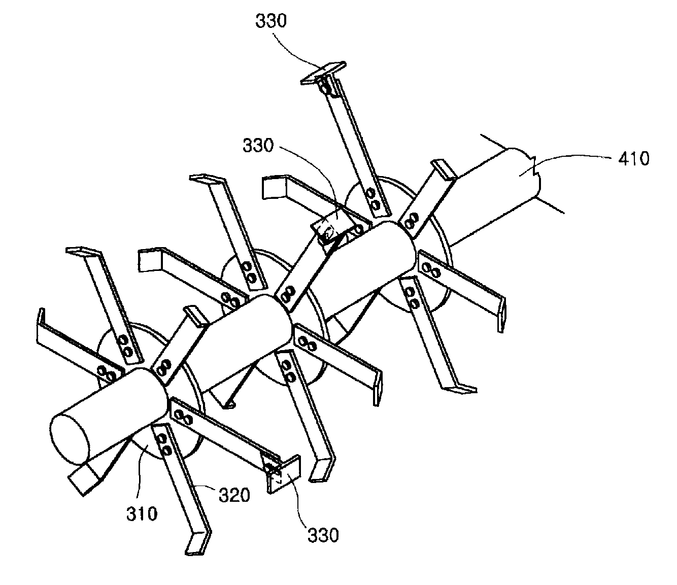
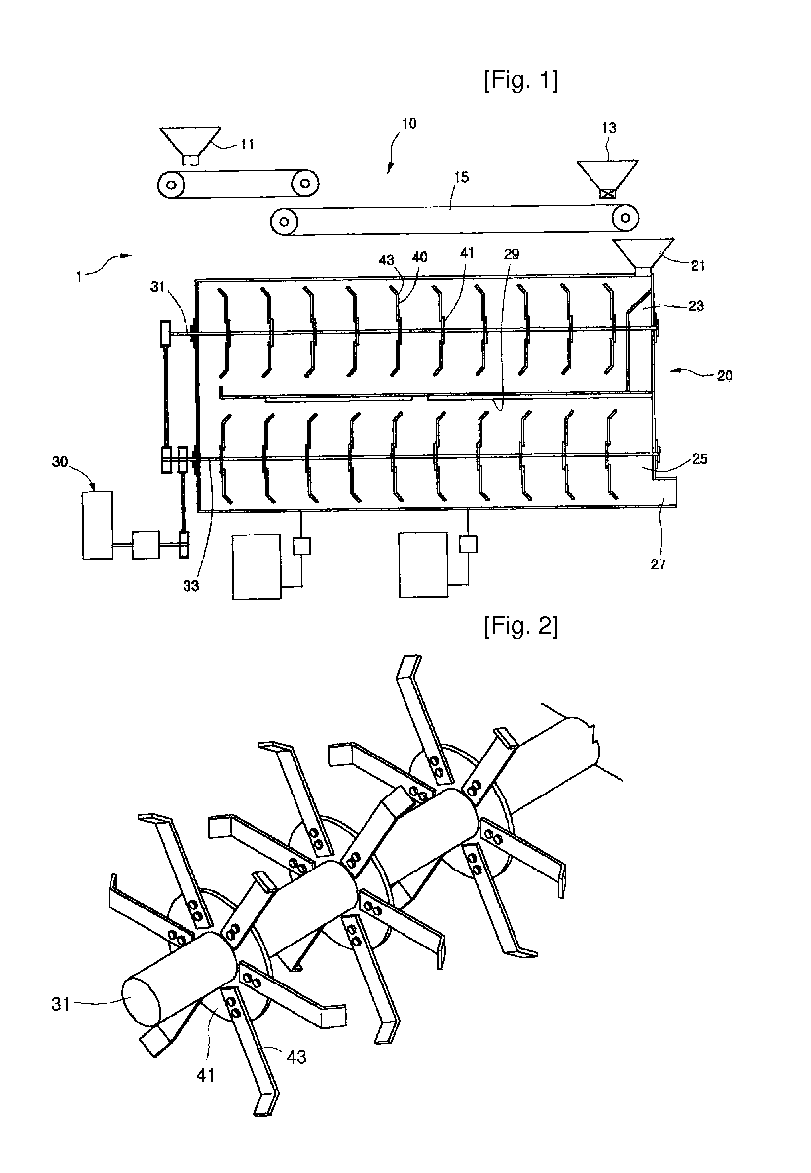
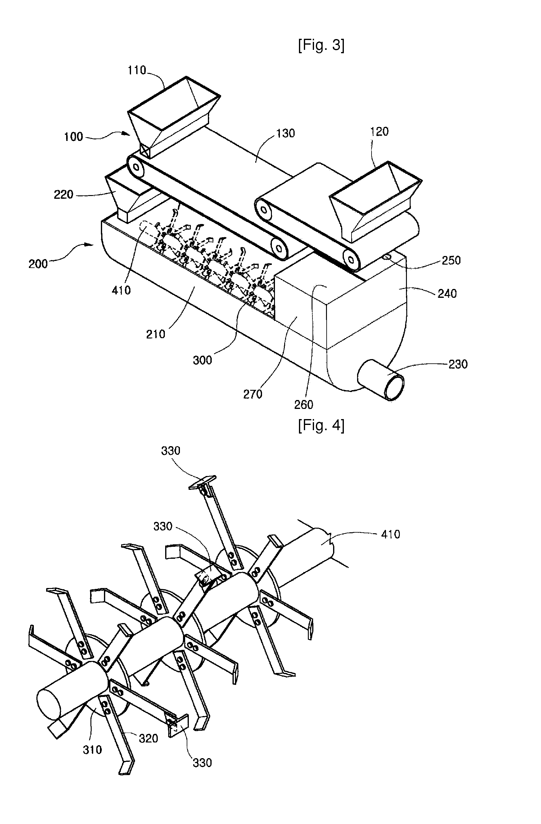
[0020]Hereinafter, a preferred embodiment of the present invention will be described in detail with reference to the attached drawings. FIG. 3 is a perspective view of a soil cement manufacturing machine according to the present invention. FIG. 4 is a perspective view showing impellers of the soil cement manufacturing machine according to the present invention. Referring to the drawings, the soil cement manufacturing machine of the present invention includes an input part 100 and a mixing part 200.

[0021]The input part 100 includes a soil hopper 110 and a cement hopper 120 for supplying soil and cement, and a conveyor belt 130, which carries soil and cement, supplied through the hoppers, to a mixing tub, in the same manner as that of a conventional soil cement machine. The construction of the hoppers and the conveyor and the coupling relationship therebetween are the same as those of the conventional soil cement machine of FIG. 1. Those skilled in the art will appreciate that various...


PUM

PropertyMeasurementUnit
discharge angleaaaaaaaaaa

Abstract

The present invention provides a soil cement manufacturing machine which prevents blades of an impeller from becoming worn and prevents soil cement from becoming stuck to and remaining in a mixing tub. The soil cement manufacturing machine includes an input part (100), which is provided for supplying soil and cement, and a mixing tub (210). The mixing tub (210) has an inlet port (220), an outlet port (230), through which mixed soil cement is discharged, and a nozzle (250) provided above the outlet port (230). The oil cement manufacturing machine further includes impellers (300), which are provided in the mixing tub (210) to mix soil and cement. Each impeller has a circular part (310) and blades (320), which are radially fastened to the circular plate. At least one impeller (300) has at least one blade which is longer than remaining blades thereof, and is provided with a scraping blade 330 having a T-shaped end.

Description

TECHNICAL FIELD[0001]The present invention relates, in general, to soil cement manufacturing machines and, more particularly, to a soil cement manufacturing machine which prevents blades of an impeller from becoming worn and prevents soil cement from becoming stuck to and remaining in a mixing tub and from thus acting as an impediment to the rotating blades during operation.BACKGROUND ART[0002]Soil cement manufacturing machines such as fan mixers are used to manufacture soil cement. However, because such machines merely agitate soil and cement, the soil and cement cannot be crushed and thus cannot be evenly mixed, thus resulting in poor soil cement.[0003]In an effort to overcome the above problem, the inventor of the present invention proposed a soil cement manufacturing machine in Korean Utility Model Registration No. 20-0295234. FIG. 1 is a perspective view showing the conventional soil cement manufacturing machine disclosed in the above Utility Model. FIG. 2 is a perspective view...

Claims


Application Information

Patent Timeline
Patent Type & Authority Applications(United States)
IPC IPC(8): B28C5/14B28C5/08
CPCB01F7/00125B01F7/00208B01F7/022B01F7/04B01F15/0229B28C5/148B01F27/0722B01F27/091B01F27/62B01F27/70B01F35/71705B28C5/14B01F27/07
Inventor LEE, TAE-HYUNG
Owner LEE TAE HYUNG
Why Eureka
Try Eureka