Bone-reaming system

a bone-reaming and system technology, applied in the field of bone-reaming system, can solve the problems of difficult to effectively operate without an invasive dislocation of the joint, wear and tear of the ball and socket created by the head of the femur and the acetabulum,

Inactive Publication Date: 2008-11-27
HOWMEDICA OSTEONICS CORP
View PDF4 Cites 16 Cited by
  • Summary
  • Abstract
  • Description
  • Claims
  • Application Information

AI Technical Summary

Problems solved by technology

Often, this is required because of the wearing or degeneration of cartilage within the joint space.
As this cartilage typically provides an articulation surface for two adjacent bones, such wearing or degeneration often causes severe pain in a patient.
The ball and socket created by the head of the femur and the acetabulum, respectively, tends to wear during the life of a patient.
Often the position and orientation of a ball and socket joint, such as the hip or shoulder, within the body make it difficult to effectively operate without an invasive dislocation of the joint.
Such a dislocation may irreversibly damage the joint capsule as well as many of the ligaments and tendons attached to and / or around the joint.
In addition, the ball and socket portions of a bone are not meant to be dislocated, and so irreparable harm to the bone surfaces of each may also occur from such dislocation.
In some cases, when surgery is necessary on the hip joint, only the acetabulum, and not the femur, may be damaged.
If the femoral head and neck are healthy, they require little to no surgical steps and merely become obstacles blocking access to the acetabulum.
Even if they are in fact damaged, the remaining femoral structure may also not be useful during operation in or on the acetabulum.
Still, in this situation it is difficult to reach the necessary portions of the acetabulum with any precision because the femoral head is positioned to block the insertion and / or use of a surgical instrument.
Penetration into or removal of any portion of the femur in this instance, though it may aid in the surgery on the acetabulum, is not always an option.
Nonetheless, often the need for operation on the acetabulum is accompanied by damage to the femur.
Although techniques have been developed to use the remaining portion of the femur to aid in the reaming of the acetabulum, the integrity of the femur may not be able to handle such manipulation and force.
Thus, for surgery on a bone socket which does not require additional medical attention directed to the mating ball, this technique is overly invasive.
Of course, this adds another wrinkle to the preparation of a particular site.
To this point such devices have not lent themselves to the preparation of site within a bone cavity, such as a socket of a ball and socket joint.

Method used


Image

  • Bone-reaming system
  • Bone-reaming system
  • Bone-reaming system

Examples


first embodiment

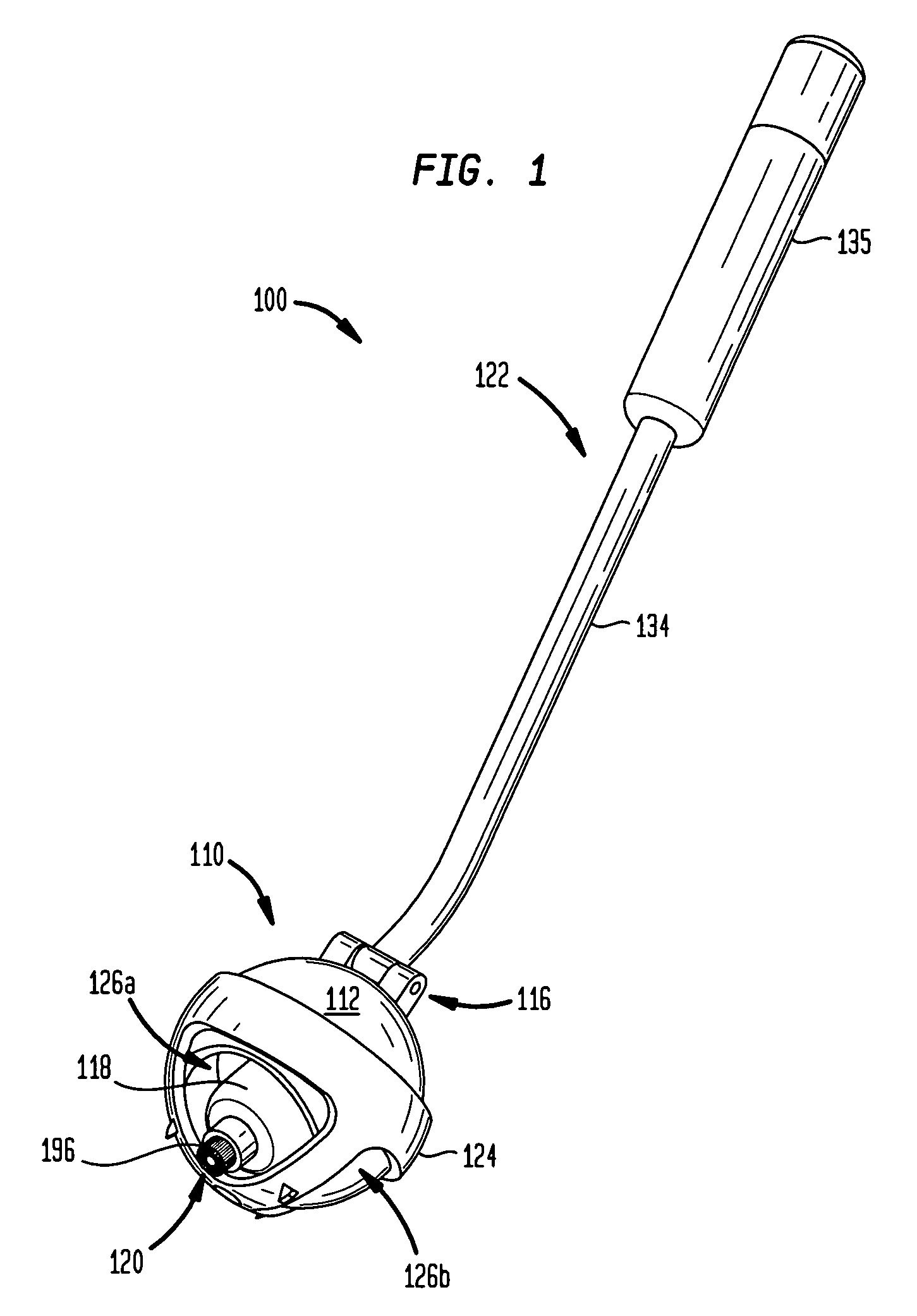
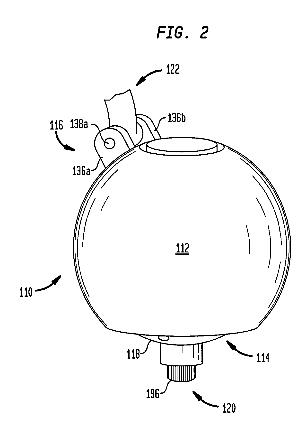
[0040]Referring to the drawings wherein like reference numerals refer to like elements, there is shown in FIG. 1, in accordance with the present invention, a bone-reaming system 100 which includes a cutting apparatus 110, a routing guide 124, and a handle 122. Cutting apparatus 110 preferably fits within routing guide 124 and is pivotally connected to handle 122 through a connection 116, shown more clearly in FIGS. 2 through 4. Routing guide 124 is preferably configured to fit within a socket or other cavity portion of a ball and socket joint, such as the acetabulum of the hip. Cutting apparatus 110 may be inserted into routing guide 124 whereby its position and orientation may be manipulated through the use of handle 122. Prior to a surgical procedure, routing guide 124 may be manufactured or configured to include one or more cutouts (shown in FIGS. 1, 3 and 4 as cutouts 126a-c) of any predefined size and shape, such that each may allow cutting apparatus 110 to cut the correspondin...

second embodiment

[0051]There is shown in FIG. 5, in accordance with the present invention, an exploded view of a bone-reaming system 200 which includes a cutting apparatus 210, a routing guide 224, and a handle 222. Cutting apparatus 210 is also shown in exploded view, where a housing 212 encloses a driving assembly 288 that drives a cutter 220. Proximate to routing guide 224 are three inserts 270 which may be implanted into the cut portions of the bone cavity. Handle 222, depicted in an exploded view, is preferably connected to cutting apparatus 210 at a connection 216. This allows for manipulation of cutting apparatus 210 through handle 222 while handle 222 is disposed outside of the patient's body.

[0052]Cutting apparatus 210 in accordance with the second embodiment is more clearly shown in an exploded view in FIG. 6. A top 250 and a bottom 252 are both preferably substantially hemispherical and together comprise housing 212 within which is disposed driving assembly 288, better shown in FIG. 7. Bo...

third embodiment

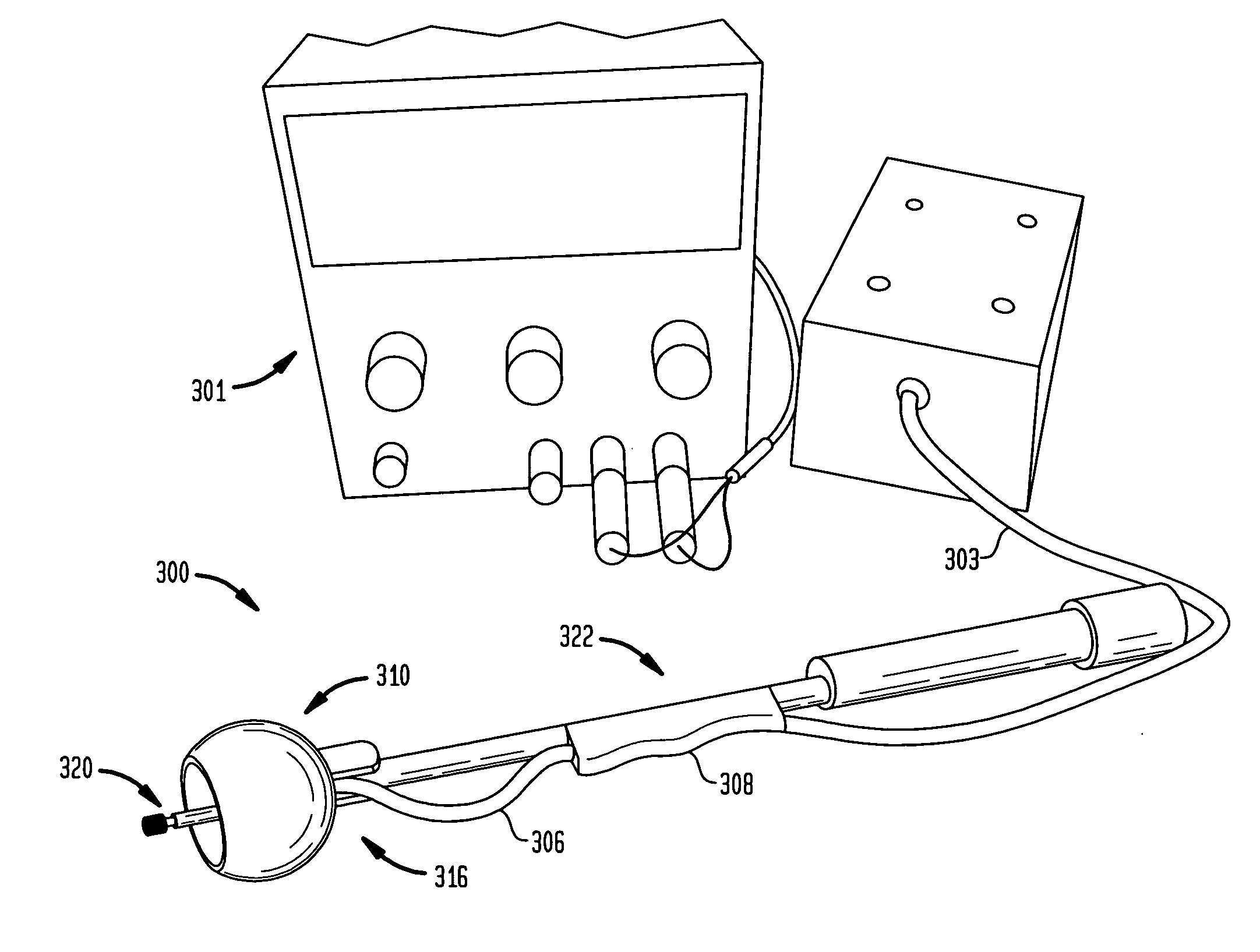
[0057]In accordance with the third embodiment, FIG. 10 depicts bone-reaming system 300 where cutting apparatus 310 and handle 322 are more clearly shown. Cutting apparatus 310 includes a housing 312 that is disposed about a motor (not shown), of which a bottom surface 390 of housing 312 is shown. Three screws 362 are disposed within three adjacent screw holes 382 in bottom surface 390 in order to mount surface 390 to the motor thereto. Handle 322 includes a stem 334 and a grip 335. Ribbon 306 extends from cutting apparatus 310 and connects to a power cord 303 through a power connection 308, which is preferably taped to handle 322 to avoid interfering with the operation of bone-reaming system 300. Ribbon 306 extends through connection 316 and may be comprised of any appropriate electrical connection device, through which a power supply 301 (shown in FIG. 9) may be connected to motor 318. Ribbon 306 is preferably flexible so as not to impede the movement of cutting apparatus 310 withi...


PUM


Abstract

A bone-reaming system for use in bone cavities which allows for a less invasive and more precise surgical procedure is disclosed. An apparatus according to such a system may include a housing, a motor disposed within the housing, and a cutter attached to the motor and extendable through the aperture, wherein the housing is capable of articulating with respect to a bone cavity so as to allow the cutter to cut at least a portion of the bone cavity. A routing guide is used in conjunction with the apparatus to provide a template through which to cut preselected portions of a bone cavity. Also disclosed is a method for using such a bone-reaming system.

Description

BACKGROUND OF THE INVENTION[0001]The present invention relates to a bone-reaming system, and more particularly, to an apparatus and method for cutting select portions of a bone cavity through the use of a removable guide and a motor-driven cutter which both fit substantially within the body of a patient.[0002]Orthopedic surgery has become more and more prevalent in recent years. Some of the more popular surgical procedures in this area involve the total or partial replacement of joints. Often, this is required because of the wearing or degeneration of cartilage within the joint space. As this cartilage typically provides an articulation surface for two adjacent bones, such wearing or degeneration often causes severe pain in a patient. Thus, it has become common place for some or all of the cartilage (and even some bone) to be removed and / or replaced with different orthopedic implants. For example, one joint which is often the subject of one or more surgeries in a patient is the hip....

Claims


Application Information

Patent Timeline
Patent Type & Authority Applications(United States)
IPC IPC(8): A61B17/00A61B18/18
CPCA61B17/1666
Inventor SCOTT, CHRISTOPHERJENKINS, II, JOSEPH C.JOHNSON, RODNEY P.
Owner HOWMEDICA OSTEONICS CORP
Why Eureka
Try Eureka