Navigated placement of pelvic implant based on combined anteversion by applying ranawat's sign or via arithmetic formula

a pelvic implant and combined anteversion technology, applied in the field of hip implants, can solve the problems of inaccurate navigation systems that reference apps, methods that do not take into account personal differences in hip mechanics and stability, etc., and achieve the effect of minimizing the occurrence of impingemen

Active Publication Date: 2008-11-27
SMITH & NEPHEW INC +2
View PDF5 Cites 31 Cited by
  • Summary
  • Abstract
  • Description
  • Claims
  • Application Information

AI Technical Summary

Benefits of technology

[0026]According to one aspect of the invention, planning includes: predicting a location of an impingement of the pelvic implant;

Problems solved by technology

However, such methods do not take into account the personal differences in hip mechanics and s

Method used


Image

  • Navigated placement of pelvic implant based on combined anteversion by applying ranawat's sign or via arithmetic formula
  • Navigated placement of pelvic implant based on combined anteversion by applying ranawat's sign or via arithmetic formula
  • Navigated placement of pelvic implant based on combined anteversion by applying ranawat's sign or via arithmetic formula

Examples


Embodiment Construction

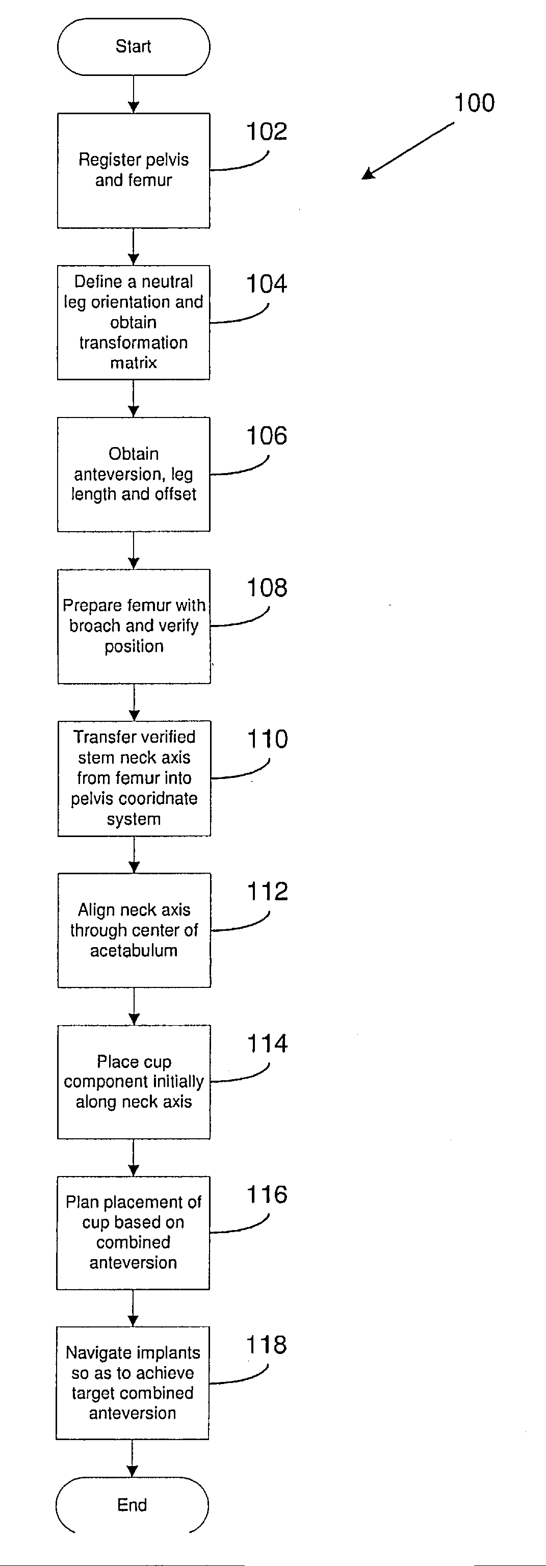
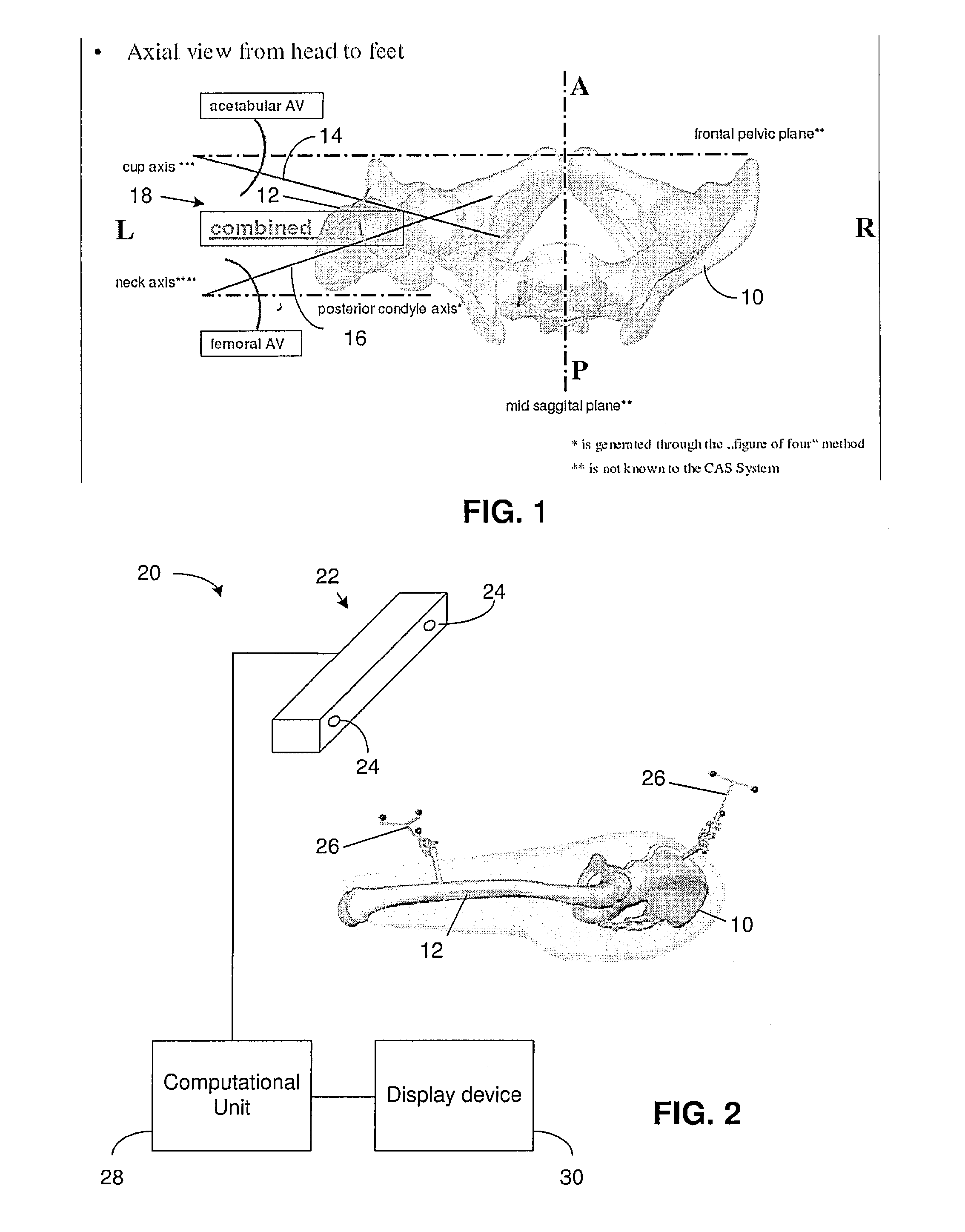
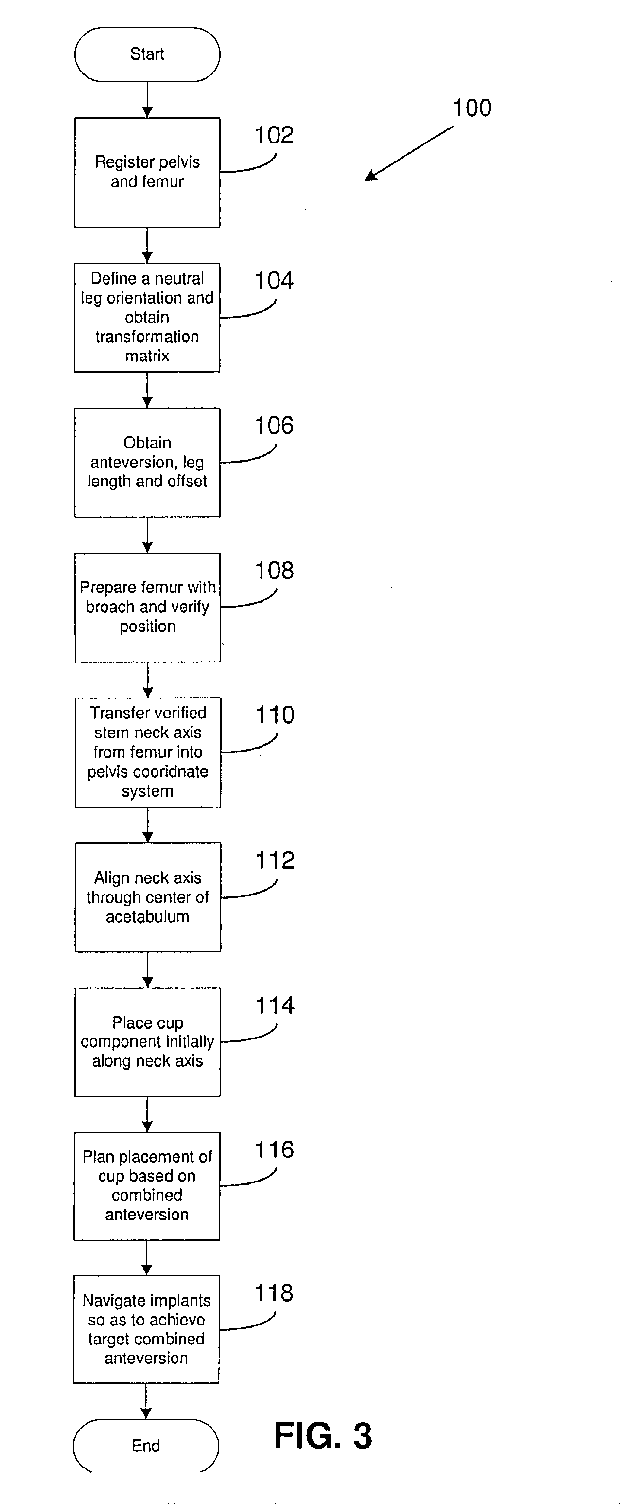
[0041]Artificial hips generally include two components; a cup that is attached to the pelvis, and a stem that is attached to the femur. The femoral stem may include a head portion coupled to an elongated stem portion via a neck portion. Conventionally, hip implants are performed by first positioning the cup, and then placing the stem in relation to the cup. A problem with this approach, however, is that the cup is free in its rotational alignments, while the stem is restricted in its rotational alignments. Thus, if there are alignment or positioning errors with the cup once it has been attached to the pelvis, there my not be sufficient positioning freedom in the stem to compensate for the mis-alignment. This can affect the overall geometry of the implanted hip joint, which can lead to impingement and possible dislocation.

[0042]The present invention enables placement of a hip implant within a patient to be planned (prior to trial fittings) such that the likelihood of impingement in t...


PUM


Abstract

A method for placing a pelvic implant including a cup and a femoral stem includes planning at least one of a location of the cup within a pelvis and a location of the stem within a femur such that a combined anteversion between a predetermined cup component and a predetermined femoral stem component satisfies a predetermined combined anteversion.

Description

FIELD OF THE INVENTION[0001]The present invention relates generally to hip implants and, more particularly, to a method and device for planning and performing the placement of a cup and femoral stem in hip implant surgery.BACKGROUND OF THE INVENTION[0002]An artificial hip joint has two main components; a prosthesis stem (also referred to as a femoral stem) and a cup. One end of the femoral stem is provided either with a spherical ball head or a prosthesis neck on which can be placed a ball head, where the ball head is designed for a close, sliding fit in a spherical recess of the cup. Together, the femoral stem with the ball head and the cup will act as a ball joint to replace the natural ball joint of the hip. The other end of the femoral stem comprises an elongated part designed to be attached to the hollow femoral canal in the patient's femur.[0003]The cup is designed to be attached to a cavity in the patient's pelvis. A hemispherical shaped, recess in the cup is linked with an e...

Claims


Application Information

Patent Timeline
IPC IPC(8): A61F2/32A61F2/36A61F2/42
CPCA61B17/1746A61B17/175A61B2017/00017A61B2017/00199A61B2017/00716A61F2/32A61F2/34A61F2/36A61F2/4607A61F2/4609A61F2002/30948A61F2002/4632A61F2002/4633A61F2002/4668A61B2090/3983A61B2034/101A61B90/36A61B2034/2055A61B2034/256A61B34/20A61B2090/067A61B34/25A61B34/10A61B2034/108A61F2/4657
Inventor WARKENTINE, BLAINEMUELLER, HEIKO
Owner SMITH & NEPHEW INC
Why Eureka
Try Eureka