
Controller of internal combustion engine

a controller and internal combustion engine technology, applied in the direction of electric control, ignition automatic control, instruments, etc., can solve the problems of unstable combustion of air-fuel mixture in the combustion chamber, and unsuitability of air-fuel mixture within the combustion chamber for any operation mode, so as to achieve smooth switching and suppress fluctuations in the output torque of the internal combustion engine

Inactive Publication Date: 2008-11-27
HONDA MOTOR CO LTD
View PDF6 Cites 22 Cited by
  • Summary
  • Abstract
  • Description
  • Claims
  • Application Information

AI Technical Summary

Benefits of technology

[0011]The invention is to provide a controller capable of, when the operation mode of a two-ignition-type internal combustion engine is switched between a compression ignition operation mode and a spark ignition operation mode, suppressing fluctuations in the output torque of the internal combustion engine, etc. and smoothly performing the switching, in view of such a situation.

Problems solved by technology

For this reason, at the time of the switching of those operation modes, the air-fuel ratio of the air-fuel mixture within the combustion chamber becomes unsuitable even for any operation mode.
As a result, troubles are apt to occur such that the combustion of the air-fuel mixture in the combustion chamber becomes unstable, or fluctuations in output torque are caused.
For this reason, troubles may be caused such that, at the time of the operation of the internal combustion engine immediately after the switching from the spark ignition operation mode to the compression ignition operation mode, the ignition timing of an air-fuel mixture is made earlier than a suitable ignition timing, excessive combustion noises is generated, or knocking occurs.
However, in the control techniques of the two-way ignition internal combustion engine as seen in the above Patent Documents 1 and 2, a control technique which is suitable at the time of the switching of the operation mode is not provided.
Thus, there is a possibility that troubles may be caused as described above.
Further, since a drive mechanism of complicated intake valves is required in the techniques seen in Patent Documents 1 and 2, the configuration of the internal combustion engine is complicated, and the optimal control of the air-fuel ratio of an air-fuel mixture, etc. is difficult due to the delay of the operation of the drive mechanism of the intake valves, etc.

Method used


Image

  • Controller of internal combustion engine
  • Controller of internal combustion engine
  • Controller of internal combustion engine

Examples


Embodiment Construction

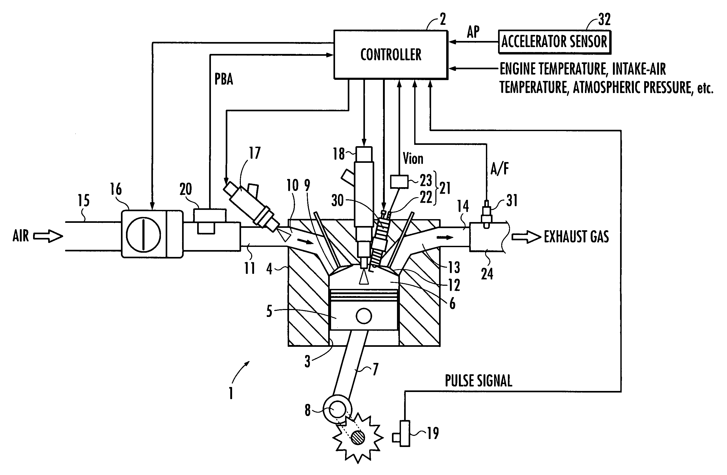
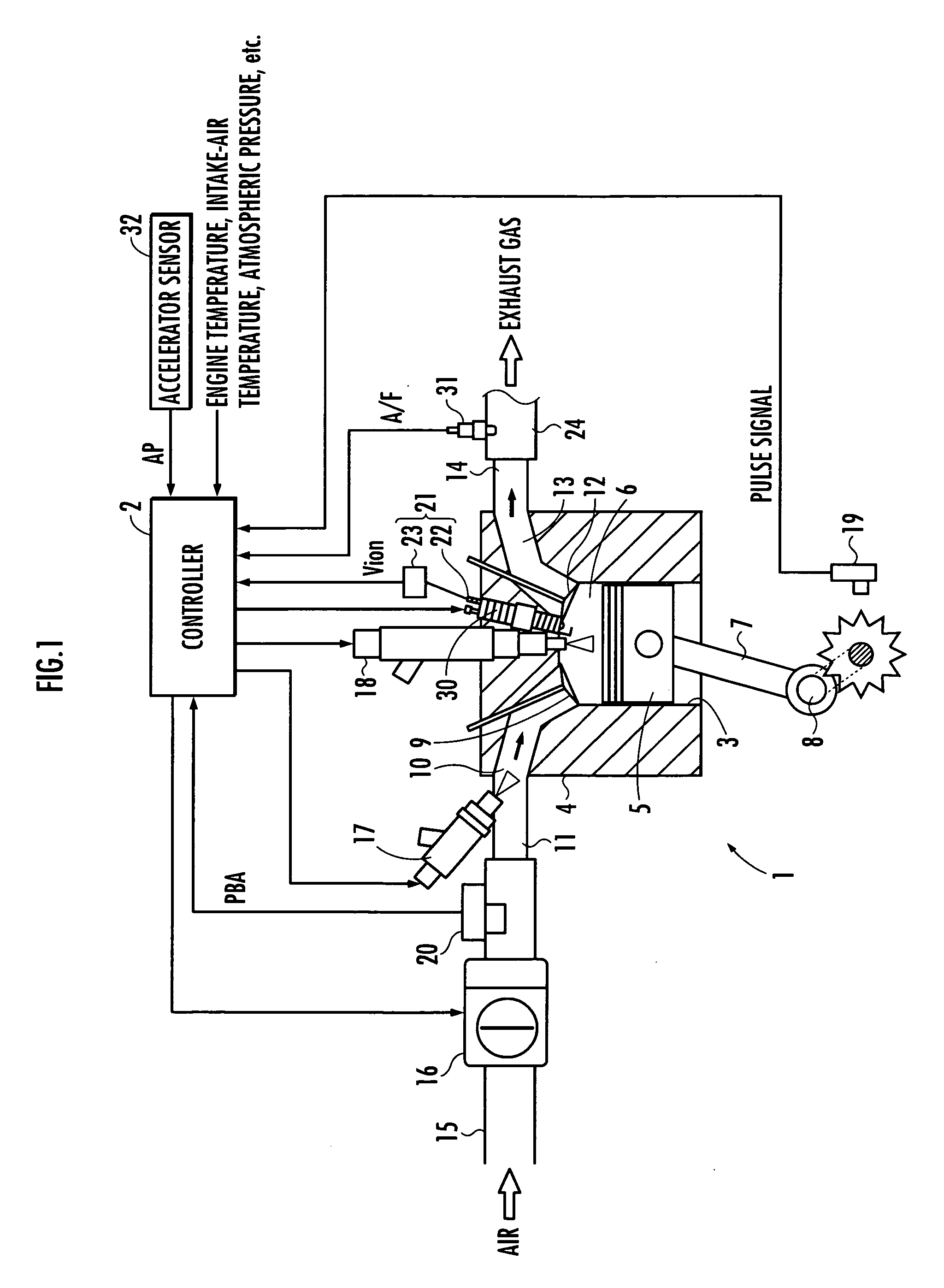
[0086]One embodiment of the invention will be explained with reference to FIGS. 1 to 30. First, with reference to FIG. 1, an overall system configuration of a controller of a homogeneous charge compression ignition engine of this embodiment will be explained. FIG. 1 is a view showing the outline of the system configuration.

[0087]In FIG. 1, reference numeral 1 represents an internal combustion engine, and reference numeral 2 represents a controller. The internal combustion engine 1 is an internal combustion engine which has a plurality of cylinders 3, for example, a four-cylinder internal combustion engine. In addition, in FIG. 1, only the schematic structure for one cylinder of the internal combustion engine 1 is typically shown.

[0088]The internal combustion engine 1 is an internal combustion engine which is operable in a compression ignition combustion operation mode in which an air-fuel mixture within a combustion chamber of each cylinder 3 is compressed, and the fuel of the air-f...


PUM


Abstract

A controller includes a first intermediate mode which, when the operation mode of an internal combustion engine is shifted from a compression ignition operation mode to a spark ignition operation mode, is interposed between both the operation modes, and a second intermediate mode which, when the operation mode of the internal combustion engine is shifted from the spark ignition operation mode to the compression ignition operation mode, is interposed between both the operation modes. An air supply amount and a fuel supply amount to a combustion chamber is controlled so that the air-fuel ratio of an air-fuel mixture becomes rich gradually in the first intermediate mode, and the air supply amount and the fuel supply amount to the combustion chamber is controlled so that the air-fuel ratio of the air-fuel mixture becomes lean gradually in the second intermediate mode. As a result, when the operation mode of the internal combustion engine is switched between the compression ignition operation mode and the spark ignition operation mode, it becomes possible to suppress fluctuations in the output torque of the internal combustion engine, etc. and smoothly perform the switching.

Description

BACKGROUND OF THE INVENTION[0001]1. Field of the Invention[0002]The present invention relates to a controller of an internal combustion engine which is operable in a compression ignition combustion operation mode in which an air-fuel mixture within a combustion chamber of a cylinder is compressed, and the fuel of the air-fuel mixture is thereby self-ignited and combusted, and a spark ignition combustion operation mode in which the fuel of the air-fuel mixture is ignited and combusted by spark ignition.[0003]2. Description of the Related Art[0004]Conventionally, as can be found in, for example, Japanese Patent Laid-Open Publication No. 2006-97603 (hereinafter referred to as “Patent Document 1”), and Japanese Patent Laid-Open Publication No. 2007-77919 (hereinafter referred to as “Patent Document 2”), an internal combustion engine (hereinafter referred to as “two-ignition-type internal combustion engine”) which is made operable in a compression ignition operation mode (so-called an HC...

Claims


Application Information

Patent Timeline
Patent Type & Authority Applications(United States)
IPC IPC(8): G06F19/00F02P5/145F02B3/06F02B11/00F02B23/10F02D9/02F02D19/08F02D41/02F02D41/04F02D45/00F02P5/15
CPCF02B1/08F02B2075/125F02D41/0002F02D41/0025F02D41/3035F02D41/3064Y02T10/36Y02T10/42Y02T10/30Y02T10/40
Inventor KUROTANI, TADASHISATO, TAKUYA
Owner HONDA MOTOR CO LTD
Learn More