Method and system for maintaining aftertreatment efficiency

a technology of aftertreatment and efficiency, applied in the direction of engines, mechanical equipment, machines/engines, etc., can solve the problems of affecting the ability of the particulate filter, and affecting the efficiency of the aftertreatmen

Active Publication Date: 2008-12-04
CATERPILLAR INC
View PDF18 Cites 23 Cited by
  • Summary
  • Abstract
  • Description
  • Claims
  • Application Information

AI Technical Summary

Benefits of technology

[0010]In one exemplary embodiment of the present disclosure, a method of compensating for variability in ash accumulation rates within an aftertreatment element of an engine exhaust system is disclosed. The method includes determining flow resistance values through the aftertreatment element. The method also includes tracking minimum flow resistance values over time. The method further includes correlating the tracked minimum flow resistance values over time, with a model of engine oil consumption rate that is based on predetermined values for model engine oil consumption. The method also includes adjusting the predetermined values based on the tracked minimum flow resistance values over time.
[0011]In another exemplary embodiment of the present disclosure, a system of compensating for variability in ash accumulation rates within an aftertreatment element of an engine exhaust system is disclosed. The system includes at least one filter section within the aftertreatment element. The system also includes a controller configured to determine flow resistance values through the aftertreatment element, track minimum flow resistance values over time, correlate the tracked minimum flow resistance values over time, with a model of engine oil consumption rate that is based on predetermined values for model engine oil consumption, and adjust the predetermined values based on the tracked minimum flow resistance values over time.
[0012]In still another exemplary embodiment of the present disclosure, a machine comprises an engine system including an exhaust system. The machine also includes an aftertreatment element, including at least one filter section, in the exhaust system. The machine further includes a control system including a controller. The controller is configured to determine flow resistance values through the aftertreatment element, track minimum flow resistance values over time, correlate tracked minimum flow resistance value over time with a model of engine oil consumption rate that is based on predetermined values for model engine oil consumption, and adjust the predetermined values based on the tracked minimum flow resistance values over time.

Problems solved by technology

Engines, including diesel engines, gasoline engines, natural gas engines, and other engines known in the art, may exhaust a complex mixture of emissions.
After an extended period of use, however, the filter material may become partially saturated with particulate matter, such as soot.
This partial saturation may hinder the ability of the particulate filter to remove particulates from the exhaust flow.
The soot may be consumed by the heat of the regeneration process.
However, a portion of the particulate matter, e.g. ash, may remain in the filter material and, over time, accumulate.
As ash accumulates, the efficiency of the particulate filter to control emissions of particulate matter may be adversely affected.
Ash derives largely from engine lubricating oil that, unavoidably, finds its way into the engine combustion chambers, and is consumed during the combustion phase of engine operation.
In addition, engine system failures, e.g. deteriorating piston rings, may result in higher than normal oil consumption and, hence, higher ash accumulation rates in an aftertreatment element.
In addition, the system of the '316 patent does not contemplate adjusting the predetermined values of the model for engine oil consumption rate based on the tracked minimum flow resistance values.
Accordingly, the system of the '316 patent may not properly take into account the impact of a major contributor to ash accumulation in a particulate trap.
Not directly accounting for the impact of consumed engine oil, may result in inaccurate determination of remaining particulate trap volume, improperly timed servicing of the particulate trap for ash removal, and adverse effects on fuel consumption when ash accumulation has been underestimated.

Method used


Image

  • Method and system for maintaining aftertreatment efficiency
  • Method and system for maintaining aftertreatment efficiency
  • Method and system for maintaining aftertreatment efficiency

Examples


Embodiment Construction

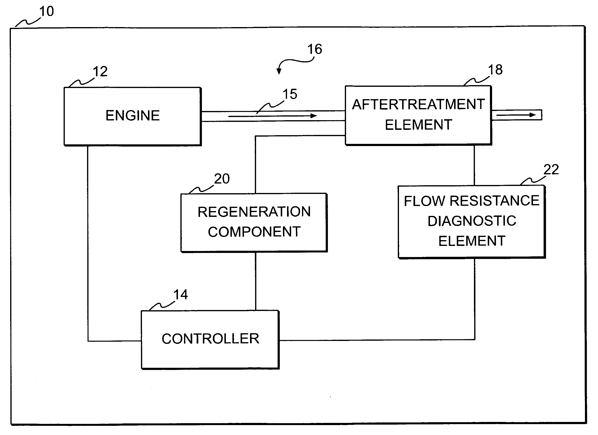
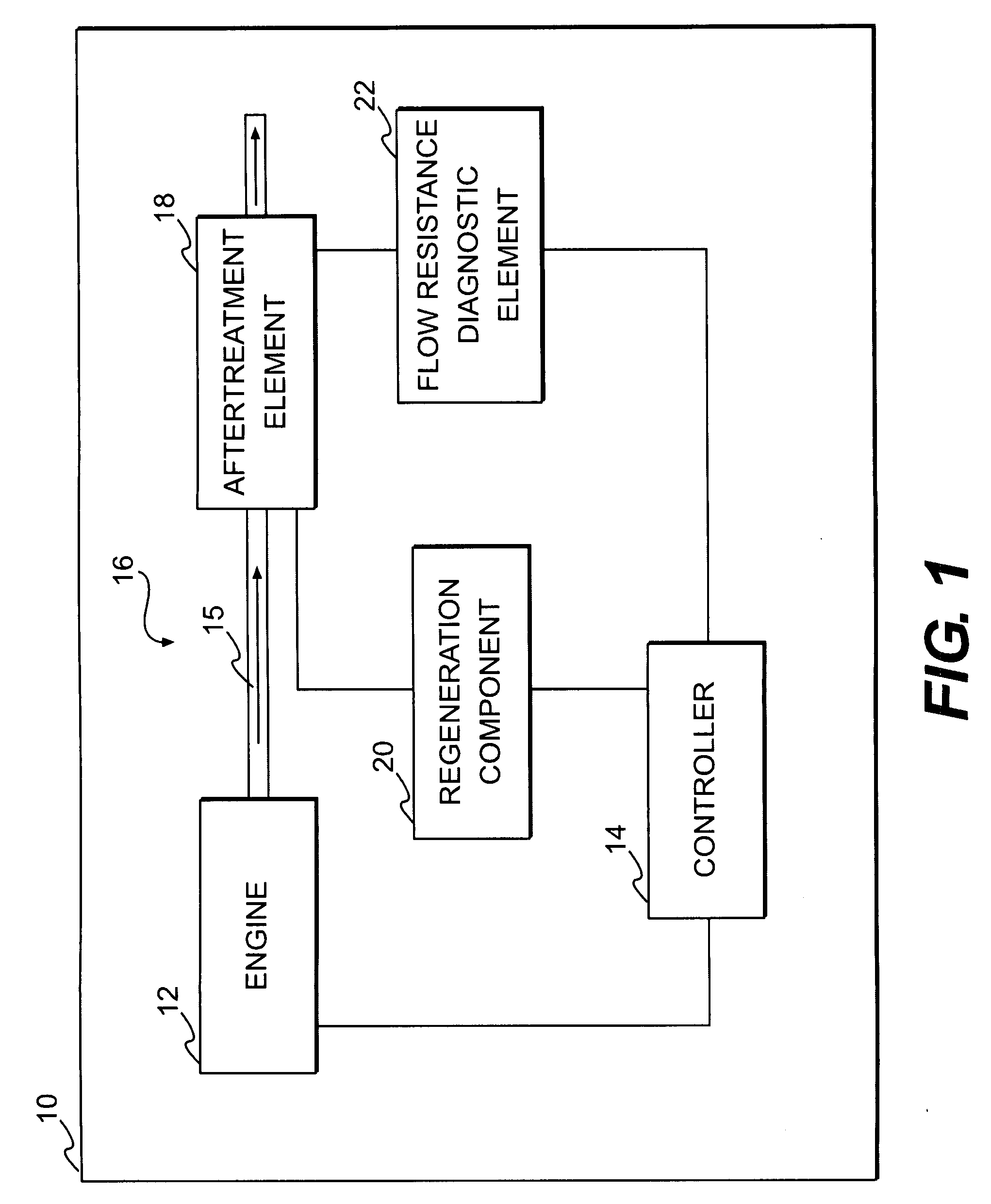
[0015]A machine 10, in which exemplary disclosed embodiments may be implemented, is diagrammatically represented in FIG. 1. Machine 10 may be any of various machines, including an on-highway truck, an off-highway haulage unit, an excavating machine, a material handling machine, a stationary power generating machine, any of various heavy equipment machines, or any other machine which may benefit from implementation of embodiments according to the disclosure.

[0016]An engine 12 may be associated with machine 10. Engine 12 may be any one of various types of engines, such as, a gasoline fueled engine, a diesel fueled engine, or a gas fueled engine. A controller 14 may be part of a control system associated with machine 10 and engine 12. Controller 14 may be programmed, via hardware, software, algorithms, etc., to monitor and control operation of engine 12, various components associate with engine 12, and / or other machine components.

[0017]Engine 12 may include an exhaust system 16. Exhaus...


PUM


Abstract

A method is provided for compensating for variability in ash accumulation rates within an aftertreatment element of an engine exhaust system. The method includes determining flow resistance values through the aftertreatment element and tracking minimum flow resistance values over time. The method also includes correlating the tracked minimum flow resistance values over time, with a model of engine oil consumption rate that is based on predetermined values for model engine oil consumption. The method further includes adjusting the predetermined values based on the tracked minimum flow resistance values over time.

Description

TECHNICAL FIELD [0001]The present disclosure is directed to reducing particulate emissions and, more particularly, to methods and systems for maintaining efficiency of aftertreatment in reducing particulate emissions.BACKGROUND [0002]Engines, including diesel engines, gasoline engines, natural gas engines, and other engines known in the art, may exhaust a complex mixture of emissions. The emissions may include both gaseous and solid material, such as, for example, particulate matter. Particulate matter may include ash and unburned carbon particles generally referred to as soot.[0003]Environmental concerns have resulted in the development of systems to treat engine exhaust. Some of these systems may employ exhaust treatment devices, such as particulate filters, to remove particulate matter from the exhaust flow. A particulate filter may include filter material designed to capture particulate matter. After an extended period of use, however, the filter material may become partially sa...

Claims


Application Information

Patent Timeline
Patent Type & Authority Applications(United States)
IPC IPC(8): F01N3/023F01N3/10
CPCF01N3/023F01N9/002F01N9/005F01N2550/04Y02T10/47Y02T10/40
Inventor SCAIFE, MARKCLEVELAND, TRENTLOWE, MICHAELOPRIS, CORNELIUSJACOBSON, EVAN
Owner CATERPILLAR INC
Why Eureka
Try Eureka