Lightweight structural component in particular for aircraft and method for its production

a technology for aircraft and structural components, applied in the direction of manufacturing tools, non-electric welding apparatuses, transportation and packaging, etc., can solve the problems of high cost of differential structure production, complex structure of stress panel/stiffening element, etc., to achieve effective and low-cost production and improve damage tolerance

Inactive Publication Date: 2008-12-04
FRAUNHOFER GESELLSCHAFT ZUR FOERDERUNG DER ANGEWANDTEN FORSCHUNG EV +1
View PDF10 Cites 41 Cited by
  • Summary
  • Abstract
  • Description
  • Claims
  • Application Information

AI Technical Summary

Benefits of technology

[0027]The invention is directed to a new kind of lightweight structural component in particular for aircraft and a method for its effective and lower-cost production that is also suitable for complex stress types. It is applicable for both straight and curved stiffening elements, features an improved damage tolerance, direct tensile strength, transverse stress loading capacity and bending resistance, and can be used even with thicker stiffening elements. Moreover, it does not require expensive additional separate production steps.
[0028]The invention is also directed to a lightweight structural component that, despite integral embodiment, features a differential failure behavior, that leads to reduced load stresses and strains in the joint zone and its immediate vicinity and that can be produced simply with modern manufacturing methods.

Problems solved by technology

The stress on the panel / stiffening element structure is very complex due to the different load originations and the static and cyclical loads dependent on many parameters.
The fact that weight-saving potentials in terms of construction methods have been largely exhausted and that the production of this type of differential structure is too expensive because of the limited riveting speed and, in addition, can hardly be improved on in qualitative terms, have a negative impact on the design of the conventionally riveted structure.
Despite better static strength and higher rigidity compared with a riveted connection, the disadvantage of a connection produced in this way lies in its lower damage tolerance which is manifested by, e.g., a higher rate of crack growth of a circumferential crack after crossing the stringer and a lower residual strength.
The reason for this is that, on reaching a welded-on stiffening element, a crack spreads out into the latter.
The reason for this defect or disadvantage is that the known integral embodiments of the connection of the stiffening elements does not provide any adequate geometric, stress-related or microstructural possibilities for stopping a crack, a less damaging crack branching or an energy dissipation near the crack opening.
The crack can thus spread unhindered into the stiffening elements.
Another defect or disadvantage is that the direct tensile strength of a stringer / panel connection laser beam-welded from both sides simultaneously decreases with increasing weld seam depth, i.e., with increasing stringer thickness.
Together with solid state mechanical influences, both of these lead to a greater under-matching in the welding zone, a broader overaged region in the heat affected zone and to an increased risk of formation of micro-hot cracks.
The disadvantage of this solution is that this embodiment is only geared to the two bay crack type of stress, i.e., the bearing of a longitudinal or circumferential crack over two rib sections or stringer divisions.
The reason for the defect is that the two disadvantages of an integrally welded structure—the lack of an effective mechanism for delaying cracks and the locally increased crack growth rate in the weld seam—are combated only with disadvantageous consequences regarding loading capacity for other types of stress, or cannot be combated at all.
One defect of the arrangement is that it is not suitable for improving the prior art with regard to the two critical stress types “tension in the direction of the head of the stiffening element” and “bending in the direction crosswise to the stiffening element.” The danger of static failure as a result of the separation of the stiffening element from the panel, in particular during transverse stress in the side shells, therefore remains.
Moreover, it has a disadvantageous effect that the reinforcements of the stiffening elements do not reduce the local crack growth rate in the weld seam and its direct vicinity.
Another defect is that the reinforcing elements cannot be applied to or inserted in the stiffening elements in an economic manner.
The reason for this is that additional production steps, such as, e.g., riveting the doubler plates, adhering the doubler plates or drilling very long through bores are necessary to apply the reinforcements, which steps are in themselves very expensive or in part even more expensive than the riveting of the stiffening elements to the panel which is to be replaced.
Furthermore, the fact that the variant with inserted tension bands is not suitable for ribs has a disadvantageous effect.

Method used


Image

  • Lightweight structural component in particular for aircraft and method for its production
  • Lightweight structural component in particular for aircraft and method for its production
  • Lightweight structural component in particular for aircraft and method for its production

Examples


example 1

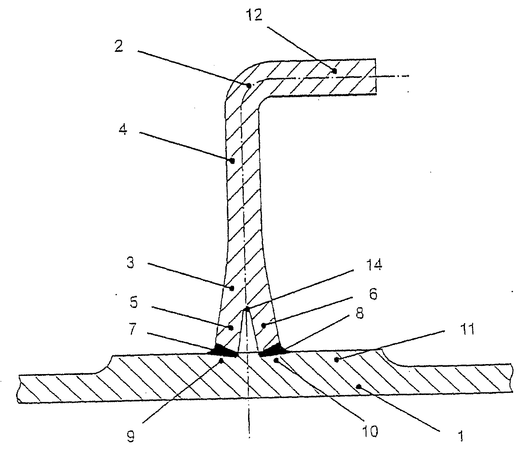
[0124]The lower fuselage of an aircraft is to be embodied with a higher dent resistance and an improved stiffness. At the same time, production costs and weight are to be reduced. To this end, a riveted construction is replaced by a laser beam-welded construction in a configuration according to the invention, as shown in FIG. 1 for the stringer / panel variant.

[0125]The panel 1 includes a panel base 11. A stringer 2 normally embodied with a stringer head 12 and stringer bar 4 features on its side facing the skin sheet 1 two side pieces 5, 6. The lower sides of the two side pieces 5, 6 extend from the stringer foot 3 and run horizontally. In this way, they rest on a level panel base 11. Both side pieces 5, 6 are connected in a material-locking and / or fixedly secured manner to the panel base 11 with two separate joint zones 7, 8. The center-lines of the joints 7, 8 can form an angle of respectively γ=approximately 20° to the surface of the panel base 11 (see FIG. 2). The joint zones 7, ...

example 2

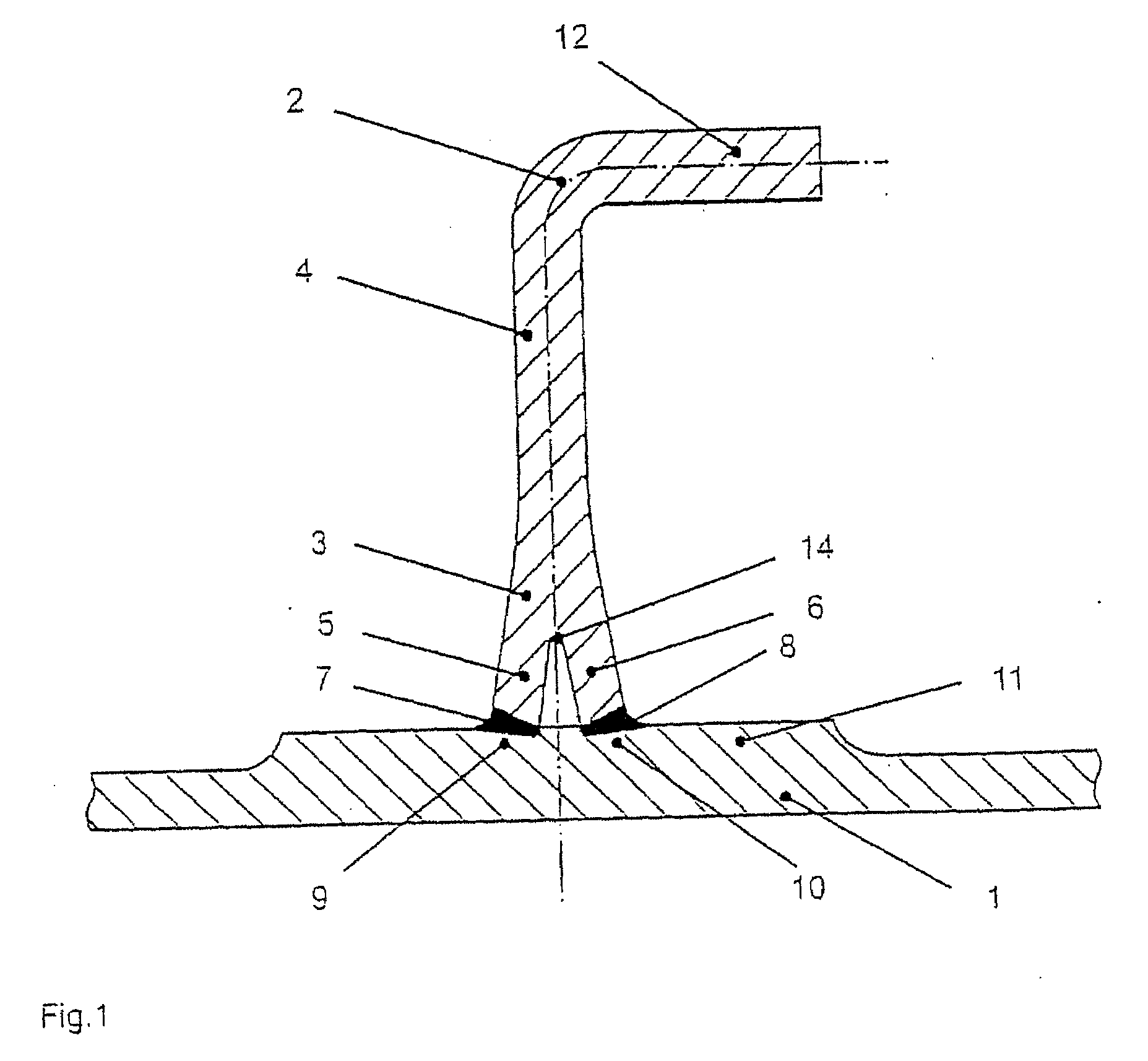
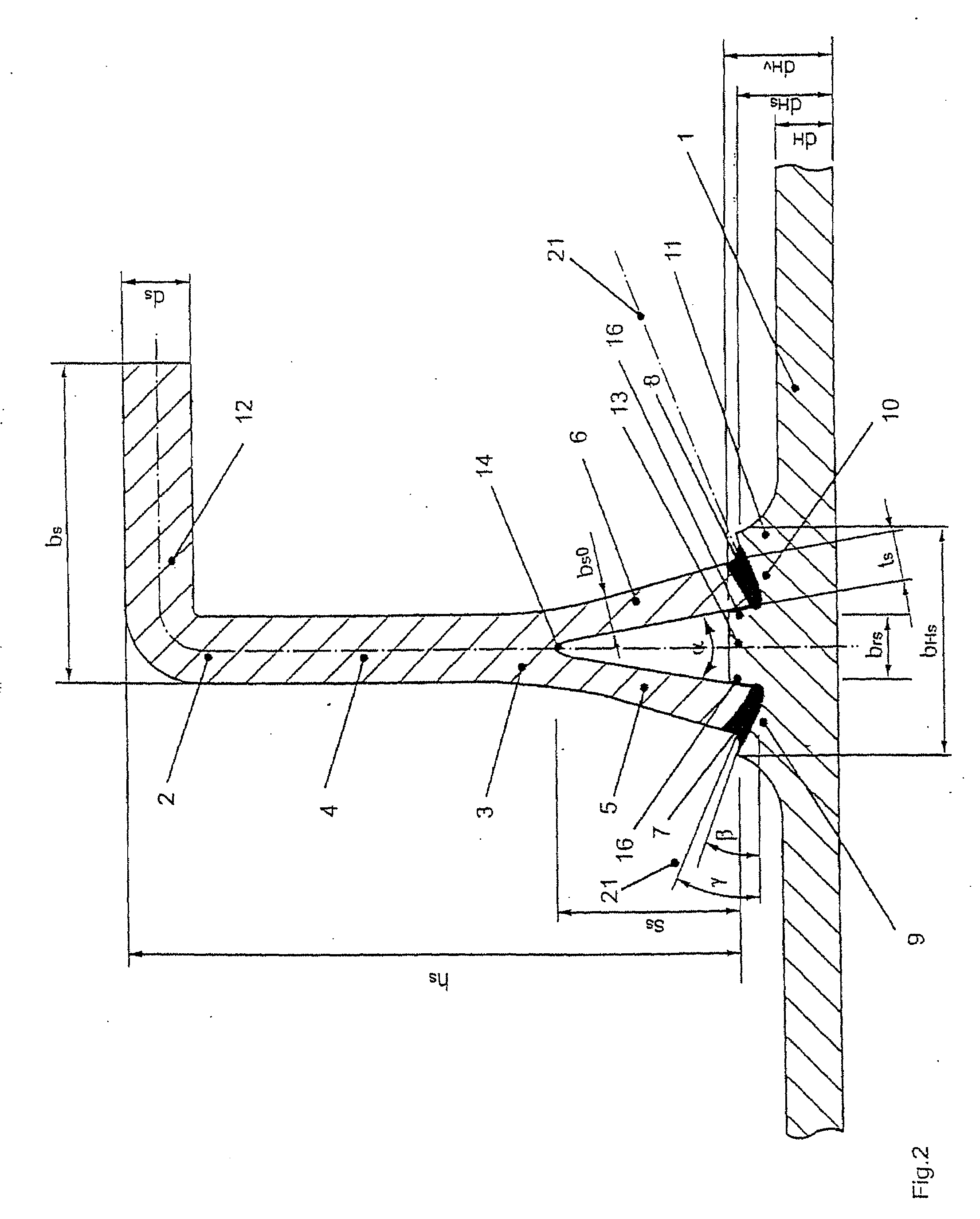
[0135]Further advantages of the invention are to be explained on the basis of a further developed embodiment that leads to a clearly improved damage tolerance behavior. It is particularly suitable for the side fuselage area but also for the upper fuselage area, i.e., for transverse stress and / or tensile stress.

[0136]One preferred geometric embodiment is shown in FIG. 2. In addition to the features specified in exemplary embodiment 1, the panel 1 also features a panel stiffening base 13. The two outer sides 16 of the panel stiffening base 13 are inclined at an angle of approx. a / 2 and are thus adapted to the inner sides of the side pieces 5, 6 that are also inclined at an angle of approx. a / 2 from the symmetric line (i.e., the center line running through stringer bar 4). The joint surfaces 9, 10 of the base 13 and of the two side pieces 5, 6 are inclined at an angle β≧approx. α / 2 with respect to the surface of the panel 1. With a weld seam angle γ≈β, the weld seam thus lies generally...

example 3

[0159]Another variant for improving the damage tolerance of welded panel / stringer connections is explained in FIGS. 10 and 11.

[0160]High tensile stresses prevail in the upper shell area along the weld seams in a stringer / skin connection. They can be reduced by stress relief elements embedded in the panel base parallel to the stringer. In one preferred embodiment they comprise wires of high-strength steel, titanium or Ni materials. Their positive effect regarding damage tolerance is due to two effects: firstly, due to their higher modulus of elasticity they put up a higher resistance to an elongation along the wire axis than the skin material surrounding them or the weld seam, so they relieve the stress on their surroundings. The crack growth rate is thus reduced when the crack approaches the stress relief element and thus the weld seam. Secondly, the residual strength is improved, because the stress relief element still remains intact after the crack has crossed the surroundings of ...


PUM

PropertyMeasurementUnit
angleaaaaaaaaaa
angleaaaaaaaaaa
total angleaaaaaaaaaa

Abstract

Lightweight structural component including at least one panel and at least one stiffening element oriented one of lengthwise and crosswise. The at least one stiffening element includes two side pieces. Each of the two side pieces is at least partially connected to the panel in a material-locking manner. The two side pieces are connected to the panel at two separate joint zones. A method of producing the lightweight structural component includes milling the at least one panel to form at least one thickened region and joining the two side pieces to the at least one panel at the two separate joint zones. This Abstract is not intended to define the invention disclosed in the specification, nor intended to limit the scope of the invention in any way.

Description

CROSS-REFERENCE TO RELATED APPLICATIONS[0001]The present application is a continuation application of parent U.S. patent application Ser. No. 10 / 757,419 filed on Jan. 15, 2004, the disclosure of which is expressly incorporated by reference herein in its entirety. The present application also claims priority under 35 U.S.C. §119 of German Patent Application No. 103 01 445.4, filed on Jan. 16, 2003, the disclosure of which is expressly incorporated by reference herein in its entirety.BACKGROUND OF THE INVENTION[0002]1. Field of the Invention[0003]The invention relates to the design and production of lightweight structural components. Objects in which its application is expedient and possible are all large-volume lightweight structures in which an essential part of the bearing pressure occurs as area load via skin sheets and which are provided with stiffening elements for load distribution, load diversion, reduction of deflection or prevention of denting or buckling. Typically such cas...

Claims


Application Information

Patent Timeline
Patent Type & Authority Applications(United States)
IPC IPC(8): B64C1/00F16S5/00B23P11/00B21D47/01B23K20/12B23K26/00B23K26/20B64C1/12
CPCB64C1/12Y10T29/49867Y02T50/42B64C2001/0081Y02T50/40
Inventor BRENNER, BERNDTWINDERLICH, BERNDSTANDFUB, JENSSCHUMACHER, JORGBRENNEIS, HARTMUTZINK, WALTER
Owner FRAUNHOFER GESELLSCHAFT ZUR FOERDERUNG DER ANGEWANDTEN FORSCHUNG EV
Why Eureka
Try Eureka