Machining robot control apparatus

a control apparatus and robot technology, applied in the direction of programmed control, manipulators, instruments, etc., can solve the problems of inability to accurately correct the position of the robot, the joint axis of the robot may deflect when the tool is used, and the position of the tool may become displaced from its intended position, so as to prevent the effect of being corrected

Inactive Publication Date: 2008-12-04
FANUC LTD
View PDF12 Cites 23 Cited by
  • Summary
  • Abstract
  • Description
  • Claims
  • Application Information

AI Technical Summary

Benefits of technology

[0023]In other words, according to the sixth to ninth aspect, the positio

Problems solved by technology

However, if the force acting between the tool and the workpiece is relatively large, for example, when performing friction welding or grinding, the joint axis of the robot may deflect when the tool comes into contact with the workpiece.
When such a deflection occurs, the position of the tool may become displ

Method used


Image

  • Machining robot control apparatus
  • Machining robot control apparatus
  • Machining robot control apparatus

Examples


Embodiment Construction

[0032]Embodiments of the present invention will be described below with reference to the accompanying drawings. Throughout the drawings, like component members are designated by like reference numerals. Further, for ease of understanding, the scale of the drawings has been changed.

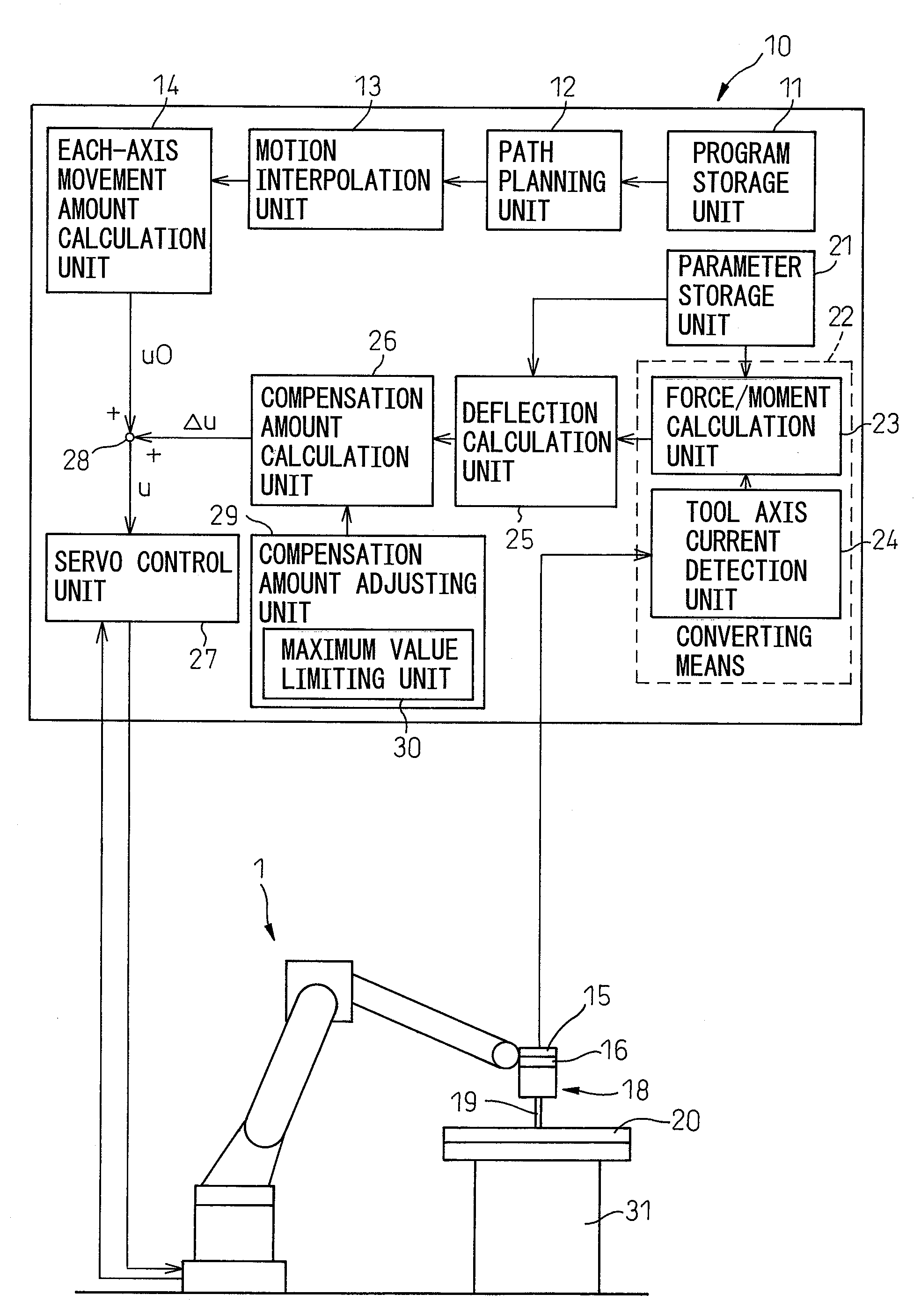
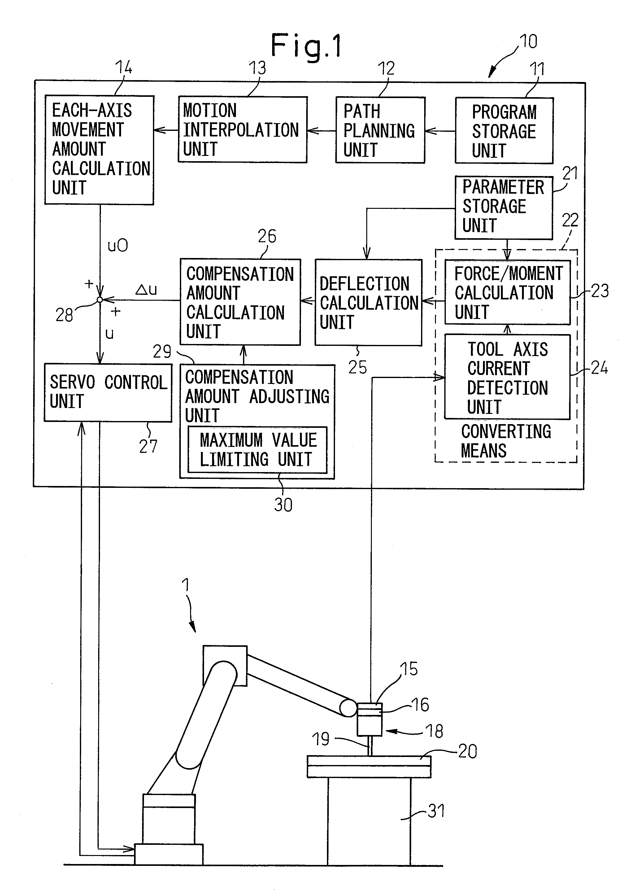
[0033]FIG. 1 is a functional block diagram of a control apparatus for a machining robot according to the present invention. As shown in FIG. 1, the control apparatus 10 is connected to the robot 1 which is, for example, a vertical articulated robot of a six-axis configuration. A tool 18 is attached to the forword end of an arm of the robot 1. In FIG. 1, the tool 18 is one used for friction welding and includes an effector 19. The effector 19 is brought into contact with a workpiece 20 fixed on a support base 31 and machines the workpiece 20. A tool 18 intended for another purpose, for example, a grinder, may be used.

[0034]As shown, a six-axis force sensor 15 is placed between the tool 18 and the arm of the...


PUM


Abstract

A control apparatus (10) for a machining robot (1) adapted to machine a workpiece (20) by coming into contact with an effector (19) of a tool (18) attached to the machining robot with the workpiece comprises: detecting means (15) for detecting a force or moment acting between the effector of the tool and the workpiece; converting means (22) for converting the force or moment detected by the detecting means into a force or moment acting on the joint axis of the machining robot; deflection calculating means (25) for calculating a deflection occurring at the joint axis of the machining robot on the basis of the force or moment acting on the joint axis of the machining robot and obtained from the converting means; and correcting means (28) for correcting at least one of a position command or a speed command for the joint axis of the machining robot in such a manner as to compensate for the deflection calculated by the deflection calculating means. Accordingly, the position of the robot is accurately corrected without being affected by the deflection of the joint axis.

Description

BACKGROUND OF THE INVENTION[0001]1. Field of the Invention[0002]The present invention relates to a control apparatus for an articulated robot. Specifically, the invention relates to a control apparatus for a machining robot that performs machining operations such as friction welding or grinding on a workpiece.[0003]2. Description of the Related Art[0004]Machining a workpiece by using a tool attached to an articulated robot, is known in the prior art and it is desirable to avoid application of excessive force to the workpiece by previously detecting the tool coming into contact with the workpiece.[0005]In the control apparatus disclosed in Japanese Unexamined Patent Publication No. 2005-125427 and Japanese Patent No. 2718688, the position of the robot is corrected by a task coordinate system in order to avoid application of excessive force to the workpiece. The control apparatus disclosed in Japanese Unexamined Patent Publication No. 2005-125427 and Japanese Patent No. 2718688 are in...

Claims


Application Information

Patent Timeline
IPC IPC(8): G05B19/404
CPCB25J9/1633B25J9/1638
Inventor NIHEI, RYOKATO, TETSUAKIKUROSHITA, TERUKI
Owner FANUC LTD
Why Eureka
Try Eureka