
Mode detecting circuit and method thereof

Active Publication Date: 2008-12-04
REALTEK SEMICON CORP
View PDF5 Cites 12 Cited by
  • Summary
  • Abstract
  • Description
  • Claims
  • Application Information

AI Technical Summary

Benefits of technology

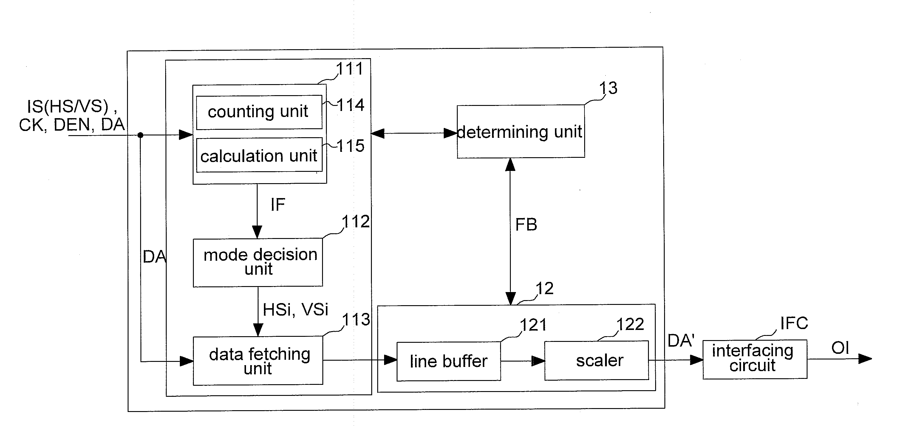
[0005]In light of above mentioned problems, an object of the invention is to provide a mode detection circuit and a method thereof. The detection circuit and the method thereof can automatically detect the resolution of an image when an image signal is inputted and can be adjusted, such as scaling up or scaling down, the resolution of the input image when the resolution of the input image is not equal to the fixed resolution of the display device so that the adjusted input image resolution is equal to the fixed resolution of the flat panel display device. Then, correctly displaying the image on the display device can be achieved.

Problems solved by technology

Furthermore, the resolution of an image signal outputted by a general video signal source, such as personal computer (PC), digital video disc / disk player (DVD Player), and so forth, may not be exactly equal to the fixed resolution of the display panel.

Method used


Image

  • Mode detecting circuit and method thereof
  • Mode detecting circuit and method thereof
  • Mode detecting circuit and method thereof

Examples


first embodiment

[0027]In the mode detection according to the invention, a clock signal generating unit that outputs a reference clock signal REF_CLK can be designed in the front end circuit 11 (not shown in the figure). When the horizontal synchronizing signal HS is inputted to the front end circuit 11, the counter of the counting unit 114 will receive it and performs counting activity according to the reference clock signal REF_CLK for measuring the signal period of the horizontal synchronizing signal HS. In order to provide more explicit description, please refer to FIG. 3A. It is assumed that in this embodiment of the invention, the inputted image signal is of 640×480 image signal mode, the frequency of the horizontal synchronizing signal HS is 31.5 KHz, and the frequency of the reference clock signal is 100 MHz. When triggered by the rising edge of the horizontal synchronizing signal HS, the counter will start counting according to the reference clock signal REF_CLK. Since the frequency of the ...

third embodiment

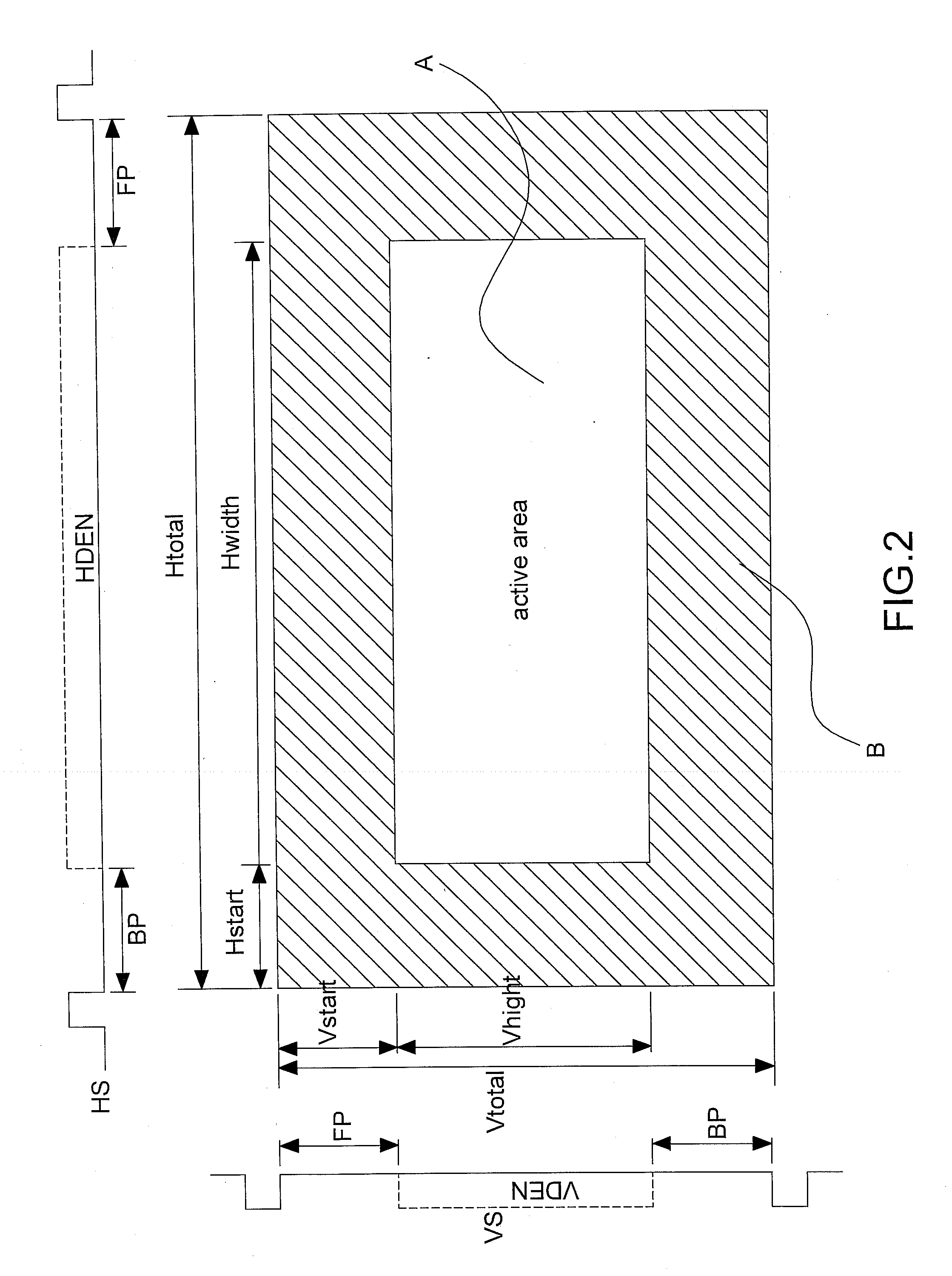
[0029]According to the mode detection of the invention, the mode detection circuit 10 can also determine the vertical resolution firstly and then performs table-looking-up in the look-up-table of the mode decision unit 112 for determining the horizontal resolution. Referring to FIGS. 4A and 4B, a clock signal generating unit can be designed in the front end circuit 11 to output a reference clock signal REF_CLK. Then the first counter of the counting unit 114 performs counting activity of the reference clock signal REF_CLK for measuring the active area time (Active_Vertical_Time, the Vhight time shown in FIG. 2) of the image signal. The second counter of the counting unit 114 performs counting activity of the reference clock signal REF_CLK for measuring the period of the horizontal synchronizing signal (Hsync_Period, the Htotal time shown in FIG. 2). The first counter and the second counter output a first counting value and a second counting value, respectively. Then, the calculating...

fifth embodiment

[0031]According to the mode detection of the invention, the horizontal resolution is determined by way of a counter counting the pixel clocks in the enabling signal HDEN to output a first counting value as the horizontal resolution of the image signal. The vertical resolution is determined by way of another counter counting the total count of pixel clocks in the active area to output a second counting value. Then a calculation unit divides the derived total count (the second counting value) by the number of pixel clocks (the first counting value) in the enabling signal HDEN to output a calculating value as the vertical resolution of the image signal. Obviously, after counting the total count of pixel clocks within the height Vhight of the active area, the vertical resolution can also be derived by dividing the obtained total count by the total count of pixel clocks between the horizontal synchronizing signals HS.

[0032]According to the description up to now, the mode detection circui...


PUM


Abstract

The invention discloses a mode detection circuit and a method thereof, for detecting an image signal, the image signal includes a horizontal resolution and the vertical resolution. The mode detection circuit includes a measuring unit, a calculation unit, and a decision unit. The measuring unit receives a clock signal and is used to count the clock signal to output a first counting value and the second counting value. The calculation unit is used to perform the calculation with the first counting value and the second counting value and thereby outputting a calculating value, wherein the calculating value outputted by the calculation unit is corresponding to the ratio of the first counting value to the second counting value. The decision unit is used to determine the horizontal resolution or the vertical resolution according to the calculating value.

Description

BACKGROUND OF THE INVENTION[0001](a) Field of the Invention[0002]The invention relates to display technology, particularly to a mode detection circuit and a method thereof.[0003](b) Description of the Related Art[0004]At present, a digital display, such as: liquid crystal display (LCD), plasma display panel (PDP), has gradually become the mainstream product in the market. In general, each of the digital display panels has a fixed physical resolution. For example, a display panel can display up to 1024×768 pixels according to the actual designed structure. Furthermore, the resolution of an image signal outputted by a general video signal source, such as personal computer (PC), digital video disc / disk player (DVD Player), and so forth, may not be exactly equal to the fixed resolution of the display panel. In other words, if a receiving circuit is applied in a liquid crystal display panel having a resolution of 1280×1024, then the receiving circuit has to perform scaling up operation o...

Claims


Application Information

Patent Timeline
IPC IPC(8): G06T17/00G09G5/02
CPCG09G5/005G09G2340/0421G09G2340/0414G06T1/60G09G3/28G09G3/36G09G2310/08
Inventor CHOU, YU-PINCHEN, SZU-PINGLIN, YU JEN
Owner REALTEK SEMICON CORP
Learn More