Contactless power receiving unit and electronic device employing the same

a technology of contactless power receiving and electronic device, which is applied in the direction of fixed transformers, inductances, transportation and packaging, etc., can solve the problems of arbitrary time-point charge differences, circuit configuration complication, etc., and achieve the effect of not complicating the configuration of the unit and simple configuration

Inactive Publication Date: 2008-12-04
SANYO ELECTRIC CO LTD
View PDF4 Cites 89 Cited by
  • Summary
  • Abstract
  • Description
  • Claims
  • Application Information

AI Technical Summary

Benefits of technology

[0023]By employing the above configuration, constant induced voltage can be supplied to a load without causing a parallel rotating magnetic field to be generated by the power supply unit. Accordingly, only a simple configuration to generate a parallel magnetic field is necessary for the power supply unit. Incidentally, although multiple power receiving coils and multiple rectifier circuits are required for the power receiving unit, these components can be configured of passive circuit elements, which thus do not complicate the configuration of the unit.
[0024]As has been described above, a power receiving unit and an electronic device employing the same is provided. To be specific, the power receiving unit has a simple configuration and is capable of generating constant induced voltage regardless of the orientation of a power receiving coil.

Problems solved by technology

Phase control circuit 82 is configured of multiple active circuit elements, which leads to a problem of complication in the circuit configuration.
This causes a problem of a difference in charged amounts at arbitrary time points, due to a difference in the amount of induced voltages at the arbitrary time points, depending on the orientation of power receiving coil 91a.

Method used


Image

  • Contactless power receiving unit and electronic device employing the same
  • Contactless power receiving unit and electronic device employing the same
  • Contactless power receiving unit and electronic device employing the same

Examples


Embodiment Construction

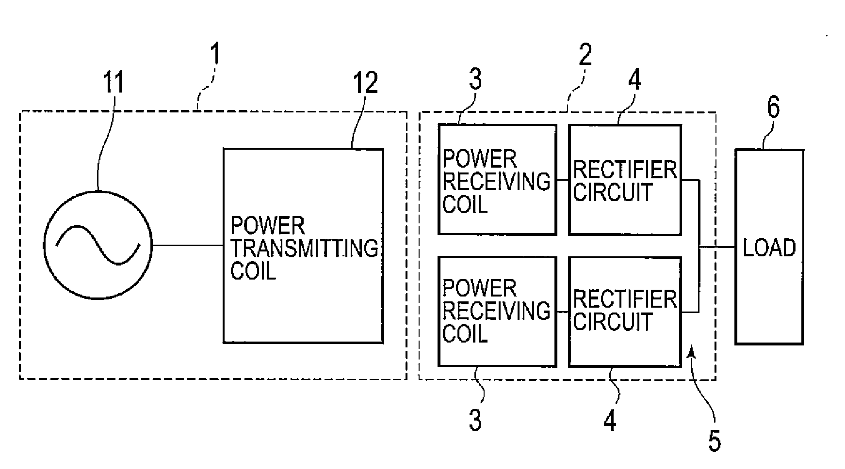
[0039]Hereinbelow, a specific description of an embodiment will be given with reference to the drawings. FIG. 1 shows a configuration of a power supply unit employing power receiving unit 2 of the embodiment. Power supply unit 1 has a simple configuration in which power transmitting coil 12 is connected to AC power source 11. Here, the configuration for generating a parallel magnetic field described above with reference to FIGS. 11A to 11C may be employed for power transmitting coil 12.

[0040]Meanwhile, as shown in FIG. 1, power receiving unit 2 includes: two power receiving coils 3; rectifier circuits 4 respectively connected to power receiving coils 3; and adder circuit 5 that adds the outputs of the two rectifier circuits 4. DC power obtained from adder circuit 5 is supplied to load 6. Incidentally, load 6 is an electronic circuit for actuating a secondary battery as a power source, or actuating an electronic device.

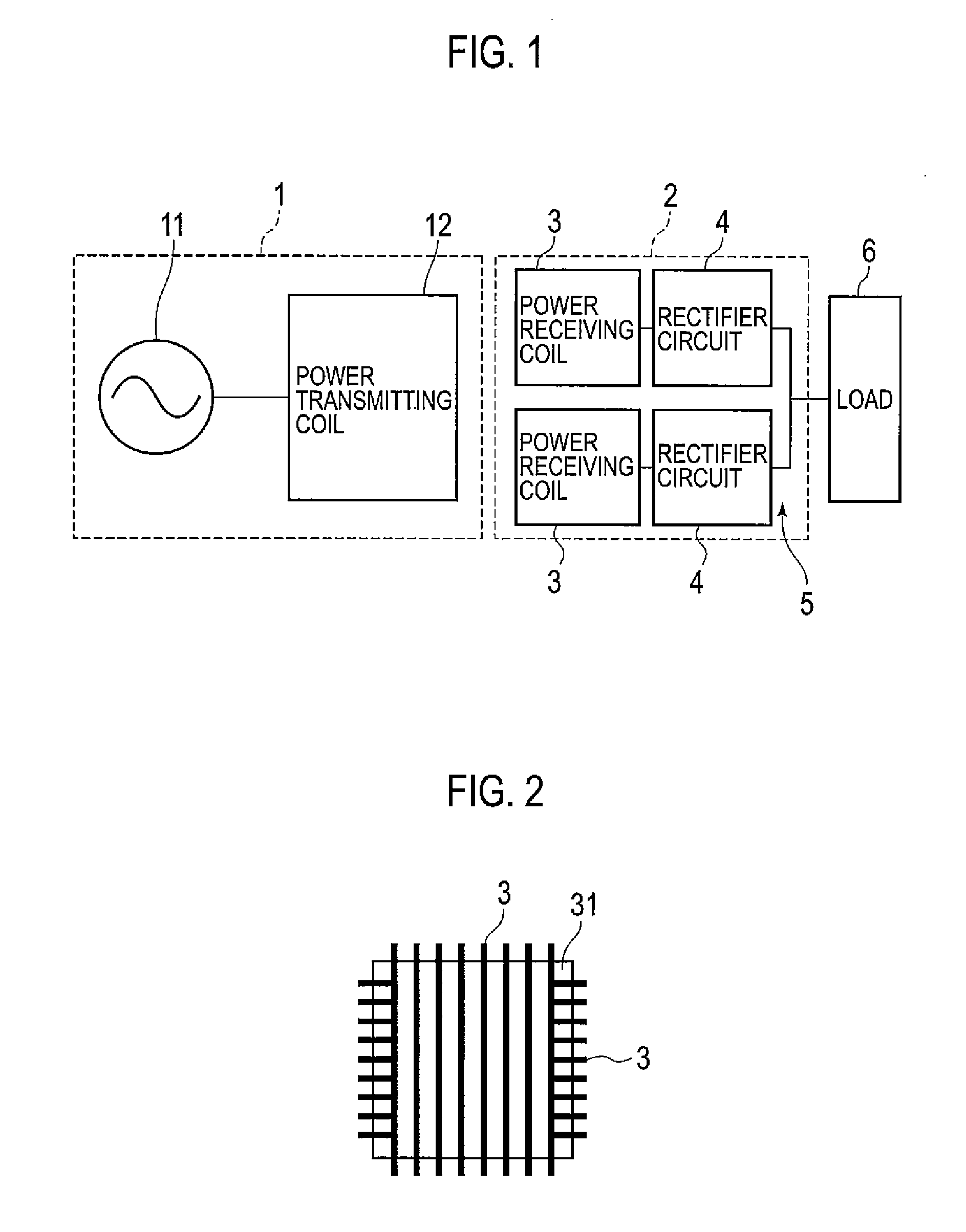
[0041]As shown in FIG. 2, a configuration may be employed in whic...


PUM

PropertyMeasurementUnit
relative angleaaaaaaaaaa
magnetic fieldaaaaaaaaaa
DC poweraaaaaaaaaa

Abstract

Provided is a contactless power receiving unit which has a simple configuration, and which is capable of generating constant induced electromotive force regardless of the orientation of a power receiving coil. Multiple power receiving coils are arranged to form certain relative angles to one another in a parallel magnetic field generated by a power supply unit. A rectifier circuit is connected to each power receiving coil. An adder circuit is configured to add DC power obtained, through the rectifier circuits, from the multiple power receiving coils, and to output resultant DC power of the addition.

Description

CROSS REFERENCE TO RELATED APPLICATIONS[0001]This application claims priority based on 35 USC 119 from prior Japanese Patent Application No. P2007-146448 filed on Jun. 1, 2007, the entire contents of which are incorporated herein by reference.BACKGROUND OF THE INVENTION[0002]1. Field of the Invention[0003]The present invention relates to a contactless power receiving unit employed to obtain necessary power in various electronic devices such as a mobile phone and a personal computer.[0004]2. Description of the Related Art[0005]Various contactless charging units are disclosed in Published PCT application No. JP2005-525705, Japanese Patent Application Publication No. 2006-333557, Japanese Patent Application Publication No. 2005-354197, and the like. Japanese Patent Application Publication No. 2005-354197 discloses a technique of transmitting energy from a primary side power supply unit to a secondary side power receiving unit by a parallel rotating magnetic field.[0006]In a contactless...

Claims


Application Information

Patent Timeline
Patent Type & Authority Applications(United States)
IPC IPC(8): H02M7/04H02J7/02H01F38/14
CPCH01F30/04H01F38/14H02J5/005H02J7/025H04B5/0037H04B5/0087H02J50/402H02J50/10
Inventor ESAKA, KOICHIROKONOTO, MASAAKI
Owner SANYO ELECTRIC CO LTD
Why Eureka
Try Eureka