Artificial socket bone

a technology of artificial teeth and sockets, applied in the field of artificial teeth, can solve the problems of unstable artificial teeth root, inability to complete the formation of alveolar bone proper (socket bone) a and bone trabeculae b, and insufficient stability of artificial teeth root, so as to achieve rapid bone tissue creation and stable implanting

Inactive Publication Date: 2008-12-04
NISHIHARA KATSUNARI
View PDF2 Cites 4 Cited by
  • Summary
  • Abstract
  • Description
  • Claims
  • Application Information

AI Technical Summary

Benefits of technology

[0016]The present invention affords the effect of artificially forming an outer cover corresponding to the alveolar bone proper (socket bone) between an implanted artificial dental root and the jawbone, and thereby encapsulating the artificial dental root and stably implanting it at the same time.
[0017]The invention affords also the effect of creating bone tissue speedily through induction of osteogenesis and hemopoiesis by stimulating mechanically undifferentiated mesenchymal cells.

Problems solved by technology

Herein, attaching an artificial dental root to the jawbone by ankylosis or osseointegration, without a buffering mechanism, is problematic as this can result in, for instance, breakage of the artificial dental root or breakage of the surrounding bone, by dint of repeated mastication.
However, complete formation of the alveolar bone proper (socket bone) A and the bone trabeculae B takes considerable time.
Alveolar bone proper (socket bone) A and the bone trabeculae B become formed after recurrent mastication over quite a number of times, but bone trabeculae do not form immediately after implant, which is problematic in that the artificial dental root is not stable, in particular, during an initial stage.

Method used


Image

  • Artificial socket bone
  • Artificial socket bone
  • Artificial socket bone

Examples


embodiment 1

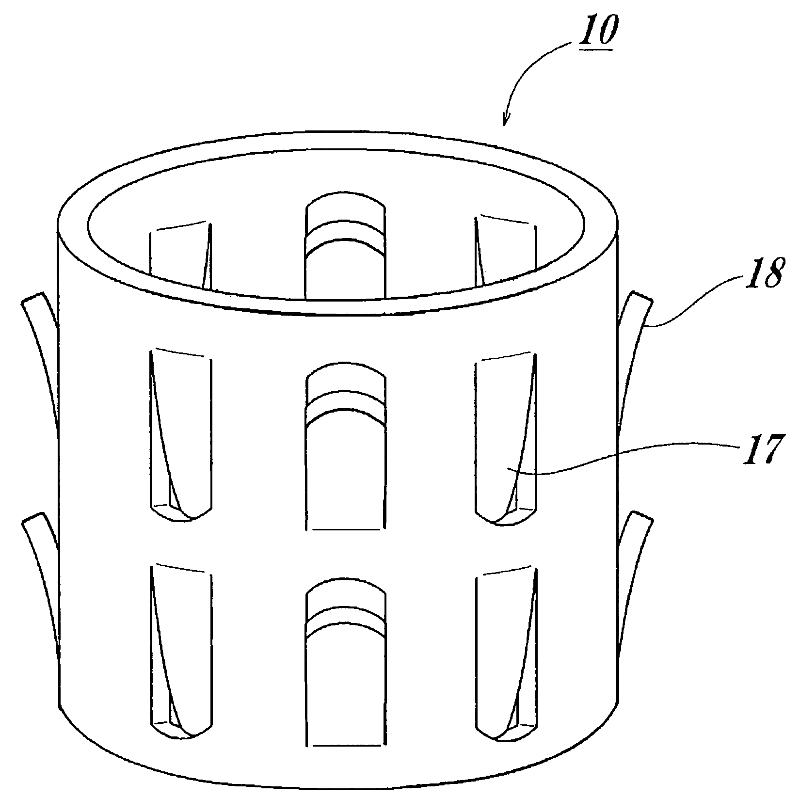
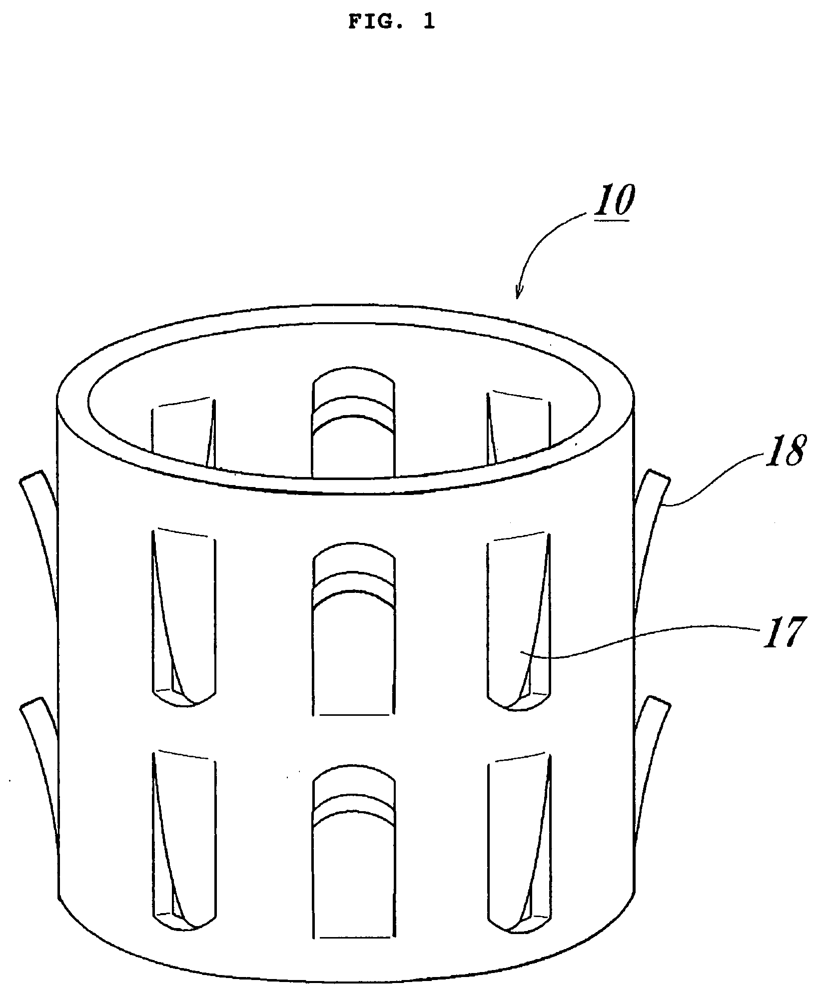
[0042]An artificial socket bone 10 according to the present embodiment, illustrated in FIG. 1, is formed to a cylindrical tubular shape having plural cuts made in the cylindrical tubular surface thereof, with protrusions 17 and 18 being formed as a result of such cuts. These protrusions include protrusions 17 protruding into the artificial socket bone and protrusions 18 bending out of the artificial socket bone.

[0043]The above plural cuts are provided equidistantly along the peripheral face of the cylindrical tube, and are arrayed equidistantly also in the axial direction. There are eight rows of protrusions spaced apart in the peripheral face direction. The protrusions 17 of cuts in some rows curve into the artificial socket bone 10, while the protrusions 18 of cuts, in rows adjacent to the former, curve out of the artificial socket bone.

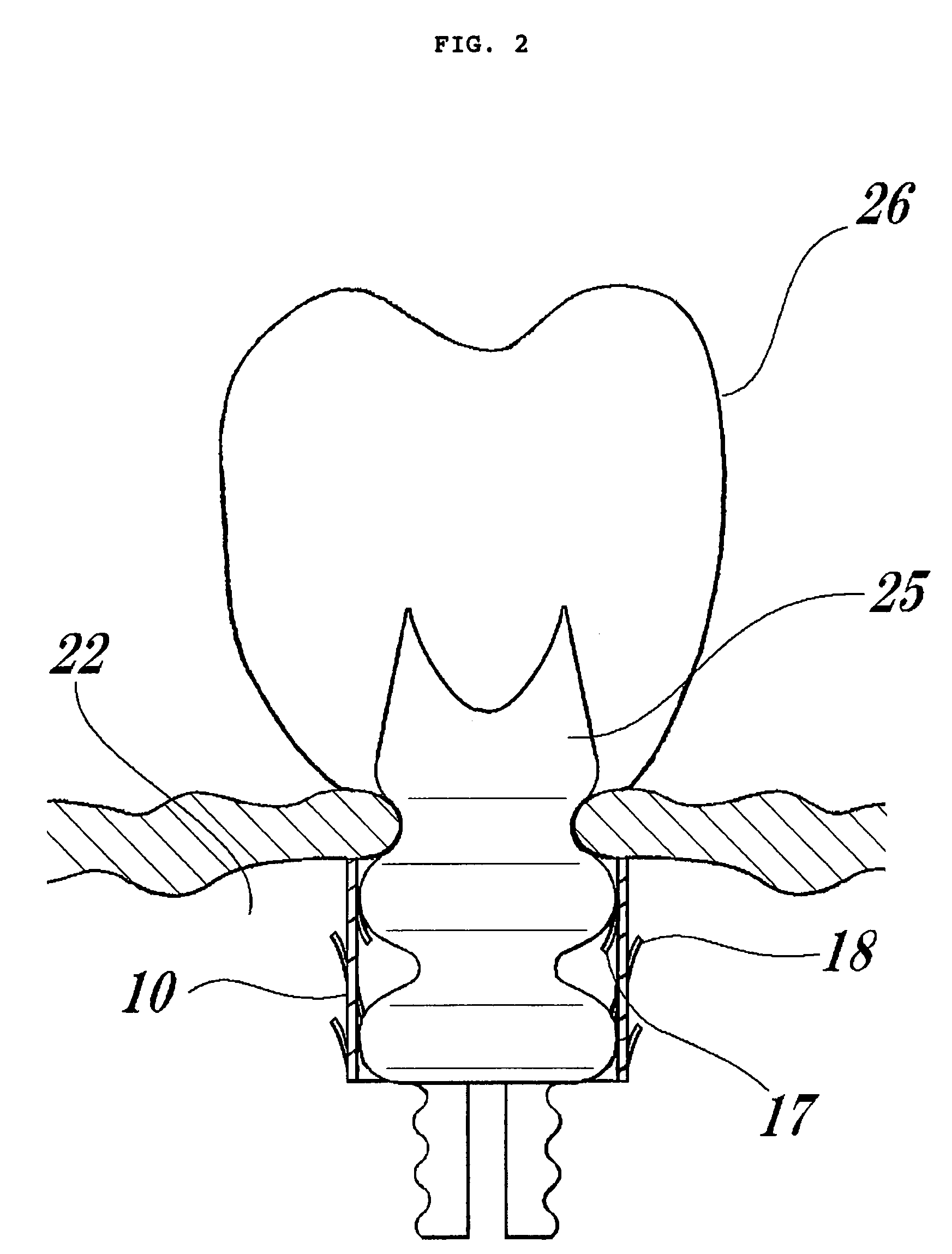
[0044]The artificial socket bone fits into an implant hole for dental roots opened in the jawbone. Herein, the protrusions 18 of the artificial so...

embodiment 2

[0049]As illustrated in FIG. 3, an artificial socket bone 30 according to the present embodiment is formed in a cylindrical tubular shape having plural cuts made in the cylindrical tubular surface thereof, with protrusions 37 and 38 being formed from such cuts. These protrusions include protrusions 37 protruding into the artificial socket bone and protrusions 38 bending out of the artificial socket bone.

[0050]The above plural cuts are provided equidistantly along the peripheral face of the tube, and are arrayed equidistantly also in the axial direction. There are eight rows of protrusions spaced apart in the peripheral face direction. The protrusions 37 of cuts in some rows curve into the artificial socket bone 30, while the protrusions 38 of cuts, in a row or rows adjacent to the former, curve out of the artificial socket bone.

[0051]Moreover, the artificial socket bone according to Embodiment 2 comprises through-holes 35 wherein part of the above cuts have no protrusions, such that...

embodiment 3

[0060]FIG. 5A and FIG. 5B show two embodiments, each showing a single sheet of a plate material 50 or 51 used in the artificial socket bone according to the present invention. A titanium alloy can be used herein as the plate material. As illustrated in FIGS. 5A and 5B, the cuts are formed in the plate material pointing alternately up and down.

[0061]The cuts 55 in the plate material 50 illustrated in FIG. 5A are substantially rectangular and have ends 54 that are punched to a circular shape. The plate material 50 may also be shaped as illustrated in FIG. 5B. The cuts 57 in the plate material 51 illustrated in FIG. 5B are substantially rectangular and have ends 58 that are configured to a deformed elliptical shape. These cuts 55, 57 and the ends 54, 58 are curved inwards or outwards to yield the protrusions of the present invention.

[0062]Also, forming through-holes by cutting from the upper or lower side with determined spacings along the axial direction of the tube allows distributin...


PUM


Abstract

An artificial socket bone used as an outer cover wholly or partially encapsulating an artificial dental root, wherein the artificial socket bone is formed in a substantially cylindrical tubular shape, with protrusions being formed through a plurality of cuts in the surface of the artificial socket bone, part or all of the protrusions being curved inwards and / or outwards of the artificial socket bone. Some of the cuts are through-holes, which have no protrusions, for letting through cells that differentiate into alveolar bone proper and bone trabeculae.

Description

FIELD OF THE INVENTION[0001]The present invention relates to an artificial socket bone for stably implanting an artificial dental root and for promoting differentiation of the cells that make up the alveolar bone proper around the artificial dental root.DESCRIPTION OF THE RELATED ART[0002]In order to support the mechanical functions of teeth, i.e. mastication and occlusion (biting), over long periods of time (60 to 80 years), humans are provided with a special structure comprising three kinds of periodontal support tissue that supports the teeth, namely 1) cementum (fibrous bone), 2) the periodontal ligament joint (dental root membrane) and 3) the alveolar bone proper (socket bone). The alveolar bone proper (socket bone) fixes the tooth to the socket bone and functions as a cushion bringing the two into contact. The surfaces of the dental root and the alveolar bone proper are fixed by cementum to the dental root membrane. At the position where the alveolar bone proper (socket bone) ...

Claims


Application Information

Patent Timeline
Patent Type & Authority Applications(United States)
IPC IPC(8): A61C13/08A61C8/00
CPCA61C8/0018A61C8/0039
Inventor NISHIHARA, KATSUNARI
Owner NISHIHARA KATSUNARI
Why Eureka
Try Eureka