Systems and methods for using polyaxial plates

Active Publication Date: 2008-12-04
SMITH & NEPHEW INC
View PDF49 Cites 255 Cited by
  • Summary
  • Abstract
  • Description
  • Claims
  • Application Information

AI Technical Summary

Benefits of technology

[0014]Certain embodiments of the invention provide plates for periarticular fractures or other non full body weight bearing applications that combine polyaxial fixation with a thinner profile and contouring that more closely conforms to bone. Such plates can be designed to achieve but

Problems solved by technology

However, although locking screws may reduce the incidence of loosening, they provide only one fixed angle relationship between the plate and the screw(s).
In short, locking screws are unidirectional, limiting their use in some instances.
For example, when treating a severe fracture, fragments may be shattered and in irregular positions.
Although a surgeon may wish to obtain the benefits of a locking screw and bone plate used together, the angle at which the locking screw extends from the plate at a certain opening may not be the angle that would allow the surgeon to “grab” (or seize, fix, or otherwise secure) the desired, random bone fragment.
However, if the surgeon desires the rigid stable construct of a locking screw and plate, the use of a non-locking screw to obtain the desired angular orientation is not necessarily optimal.
However, because these combination slots are only partially threaded, the locking screw(s) may not be able to maintain the fixed angular relationship between the screw(s) and plate under physiological loads.
This can result in loss of fixation or loss of established intraoperative plate orientation.
Moreover, the locking screw can still only be inserted at a single angle—the predetermined angle defined by the manufacturer.
Additionally, current bone plate and screw systems still limit a surgeon's ability to both (a)

Method used


Image

  • Systems and methods for using polyaxial plates
  • Systems and methods for using polyaxial plates
  • Systems and methods for using polyaxial plates

Examples


Example

[0102]I. Plates with Polyaxial Openings Generally

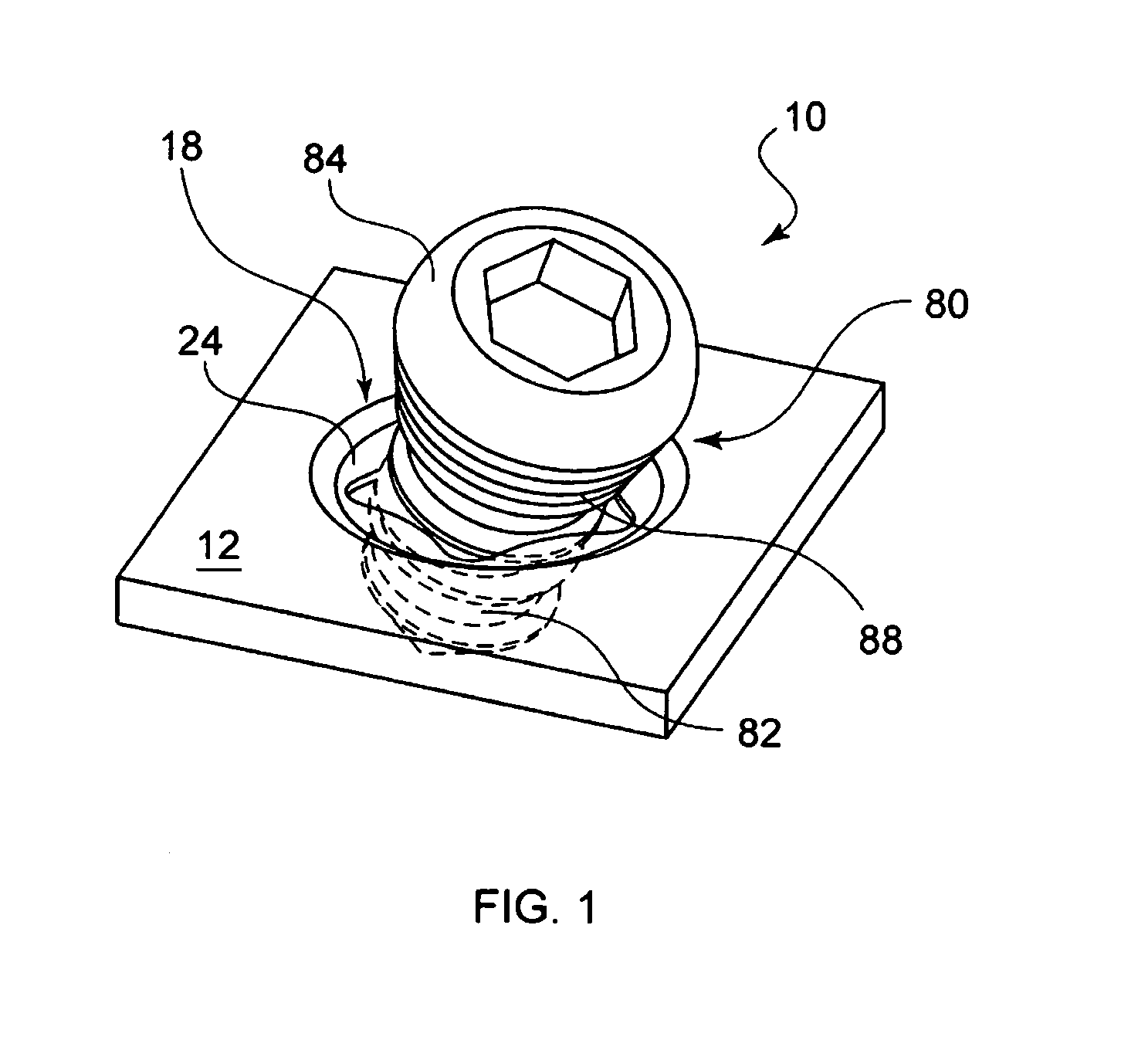
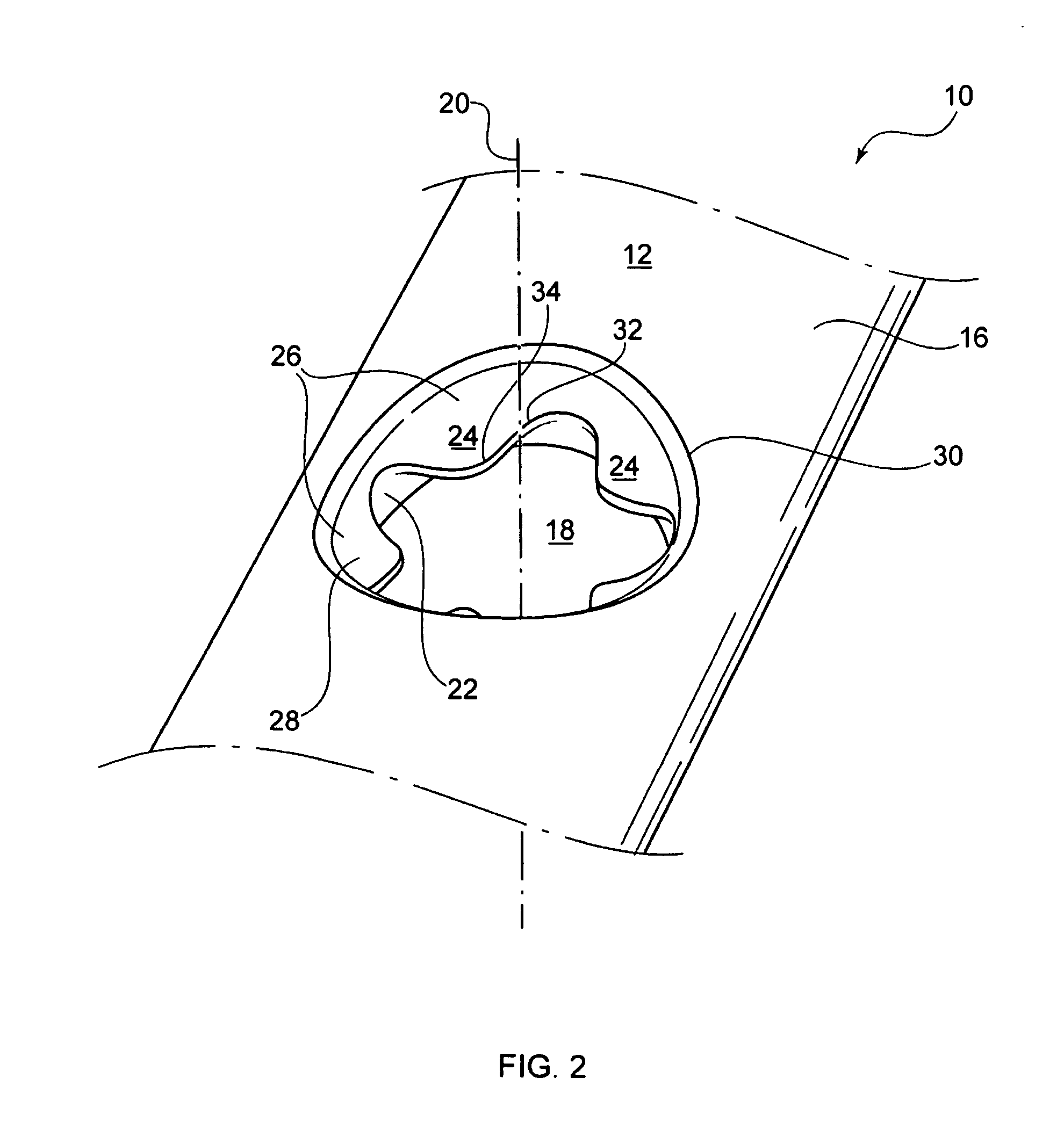
[0103]Embodiments of the present invention provide a bone fixation assembly that can accept and fix fasteners at a plurality of angles. A specific embodiment of a bone fixation assembly 10 is shown as a bone plate 12 and fastener 80 in FIG. 1. As shown in more detail in FIGS. 2-4, bone plate 12 has a lower surface 14 and an upper surface 16 and one or more openings 18 that extend from the lower surface 14 to the upper surface 16.

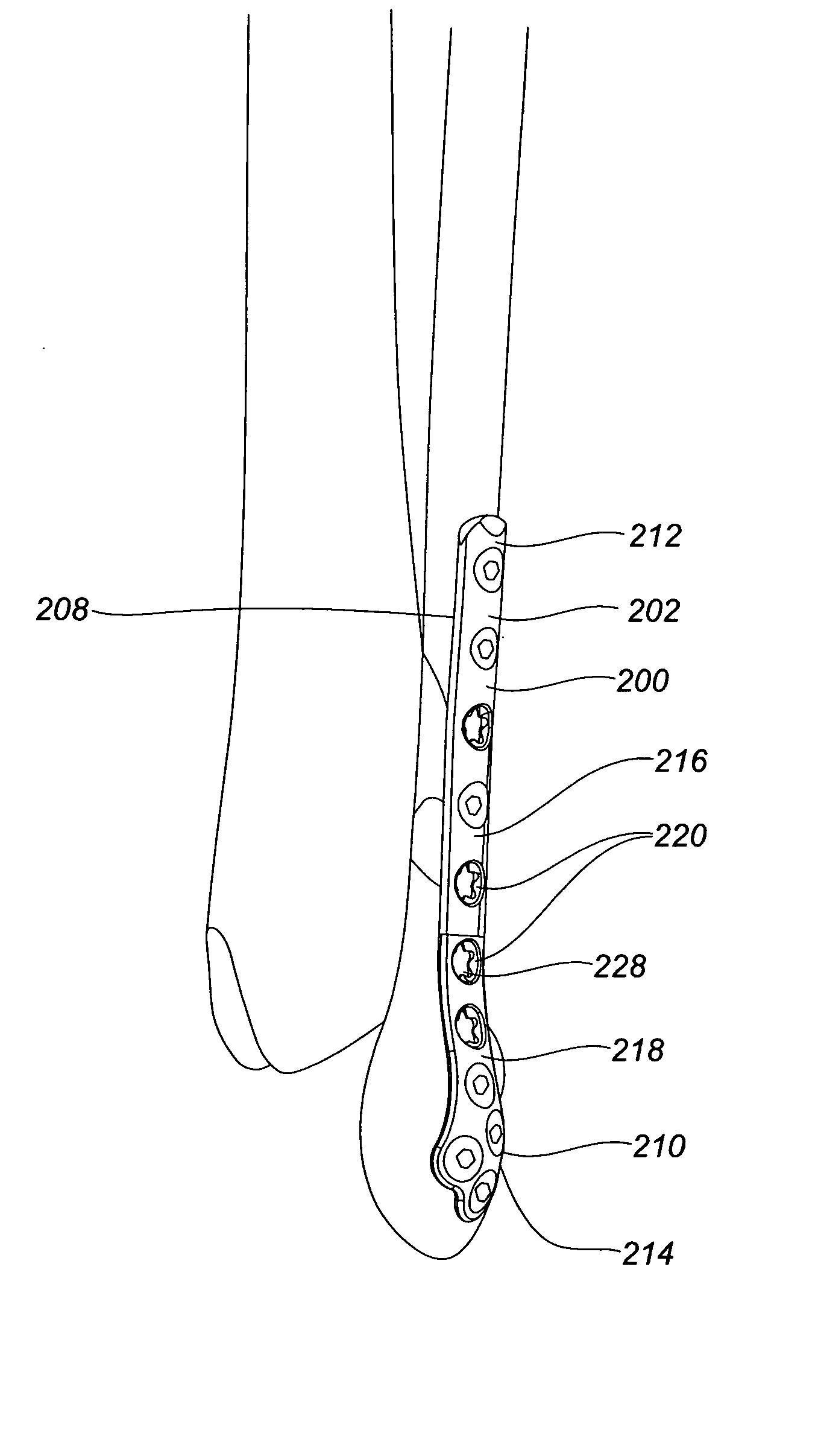
[0104]The embodiments described herein may be used in connection with any type of bone plate, non-limiting examples of which are shown in FIGS. 11-15. Plate 12 may be adapted to contact one or more of a femur, a distal tibia, a proximal tibia, a proximal humerus, a distal humerus, a clavicle, a fibula, an ulna, a radius, bones of the foot, or bones of the hand. The bone plate may be curved, contoured, straight, or flat. It may be a periarticular plate or a straight plate. An example of a straight plate in show...


PUM


Abstract

Certain embodiments of the invention provide plates for treating periarticular fractures or other non-full body weight bearing applications that combine polyaxial fixation with a low profile and enhanced contouring that more closely conforms to bone. Such plates can be designed to achieve buttressing effect and/or to be used in a reinforcement mode. Other features can be combined with these. Such plates can be created for use on bone sites such as on a tibia, fibula, metatarsal, calcaneous, other foot bone, humerus, radius, ulna, spinal, maxillofacial, as well as sites on other bones.

Description

[0001]This application is a continuation-in-part of U.S. Ser. No. 11 / 996,795 filed Jan. 25, 2008 which is the U.S. National Phase of International Application No. PCT / US2006 / 028778 filed Jul. 25, 2006, which claims the benefit of U.S. Provisional Application Ser. No. 60 / 702,231 filed Jul. 25, 2005 titled “Locking Screw,” the entire contents of which are hereby incorporated by reference.BACKGROUND OF THE INVENTION[0002]This invention relates generally to orthopedic fixation devices and bone plating systems for fracture fixation, and particularly to systems and methods for using bone plates that provide polyaxial fixation of fasteners.[0003]Bone fractures are often repaired by securing a bone plate across the fracture. Depending upon which bone is to be treated, the bone plate may be straight or curved to match the contour of the bone for which it is designed. Bone plates may also be provided in many shapes and sizes. In cases where a bone is severely comminuted or if bone segments ar...

Claims


Application Information

Patent Timeline
IPC IPC(8): A61B17/70
CPCA61B17/74A61B17/8057A61B17/8061A61B17/8033A61B17/8605A61B17/863A61B2017/00004A61B17/8085A61B17/8052
Inventor AUSTIN, GENE EDWARDHARMON, JON ANDREWPETTEYS, TIMOTHY J.RUSSELL, THOMAS ANTHONYTORNETTA, PAULRICCI, WILLIAM
Owner SMITH & NEPHEW INC
Why Eureka
Try Eureka