
Percutaneous interspinous process device and method

a technology of process device and interspinous vein, which is applied in the field of spinal conditions, can solve the problems of pain, weakness, burning sensation, loss of bladder or bowel function, or paralysis, and achieve the effect of increasing the distance between adjacent spinous processes

Active Publication Date: 2008-12-04
K2M
View PDF99 Cites 80 Cited by
  • Summary
  • Abstract
  • Description
  • Claims
  • Application Information

AI Technical Summary

Benefits of technology

The patent describes a device and method for treating spinal conditions by inserting a device between adjacent spinous processes. The device has two sections that can be joined together to maintain a space between the spinous processes. The method involves distracting the adjacent spinous processes and inserting the device from opposite sides of the spine. The technical effect of this invention is to provide a minimally invasive method for treating spinal conditions that preserves the posterior interspinous ligaments.

Problems solved by technology

The compression of the spinal cord, the spinal nerve roots, or both, generally results in pain, weakness, numbness, burning sensations, tingling, and, in particularly severe cases, may cause loss of bladder or bowel function, or paralysis.

Method used


Image

  • Percutaneous interspinous process device and method
  • Percutaneous interspinous process device and method
  • Percutaneous interspinous process device and method

Examples


Embodiment Construction

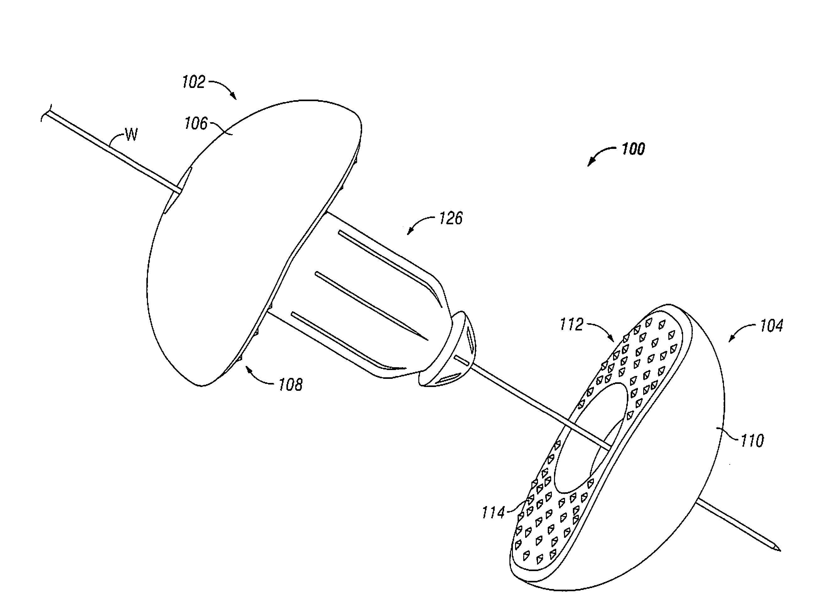
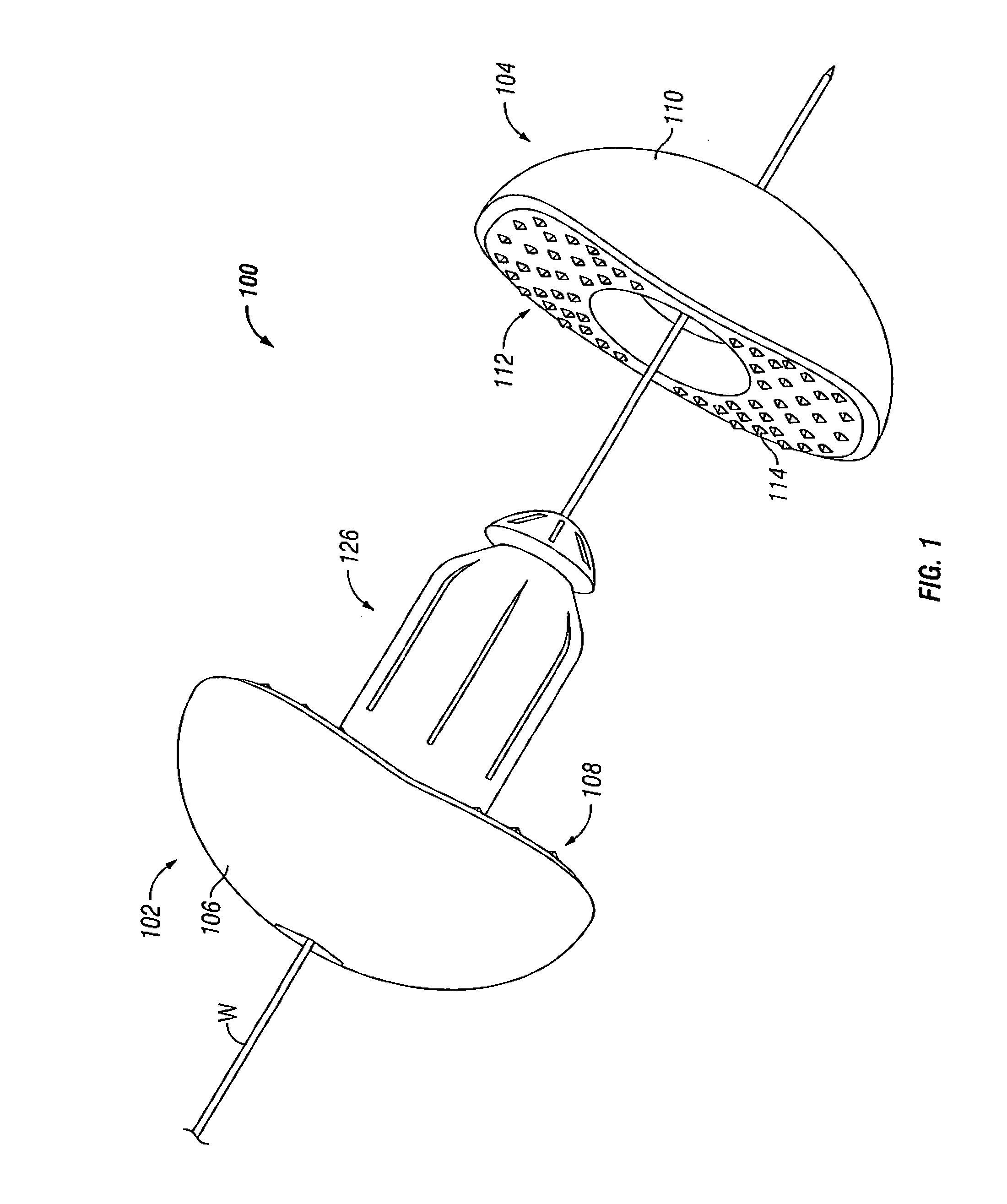
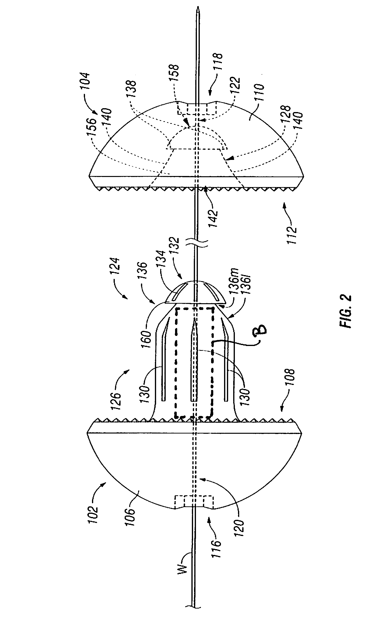
[0028]Embodiments of the presently disclosed percutaneous interspinous process device will now be described in detail with reference to the drawings, wherein like reference numerals identify similar or identical elements. In the drawings and in the description that follows, the term “proximal” will refer to the end of a surgical instrument or device that is closest to the operator, while the term “distal” will refer to the end of the instrument or device that is farthest from the operator. In addition, the term “cephalad” is used in this application to indicate a direction toward a patient's head, whereas the term “caudad” indicates a direction toward the patient's feet. Further still, for the purposes of this application, the term “medial” indicates a direction toward the middle of the body of the patient, whilst the term “lateral” indicates a direction toward a side of the body of the patient (i.e., away from the middle of the body of the patient). The term “posterior” indicates a...


PUM


Abstract

A percutaneous interspinous process device for treating spinal conditions includes a first section, a second section, and a locking mechanism. The first section defines a first lateral surface, a first medial surface and a first lumen extending from the first lateral surface to the first medial surface. The second section defines a second lateral surface, a second medial surface and a second lumen extending from the second lateral surface. The locking mechanism includes an elongate member protruding from the first medial surface of the first section and a medial recess defined in the second medial surface of the second section. The medial recess is configured for securely receiving at least a portion of the elongate member. The elongate member is configured to define a space between adjacent spinous processes and maintain a predetermined distance between adjacent spinous processes.

Description

CROSS-REFERENCE TO RELATED APPLICATION[0001]This application claims priority to, and the benefit of, U.S. Provisional Patent application 60 / 933,028, filed on Jun. 4, 2007 the entire contents of which are incorporated herein by reference.BACKGROUND[0002]1. Technical Field[0003]The present disclosure relates generally to devices and methods for treating spinal conditions, and more particularly, for treating spinal compression with percutaneous spinal devices implanted between adjacent spinous processes.[0004]2. Background of the Related Art[0005]A significant number of people suffer from a condition known as spinal stenosis. Spinal stenosis is a progressive narrowing of the spinal canal that causes compression of the spinal cord. Each vertebra in the spinal column has an opening that extends through it. These openings are aligned vertically to form the spinal canal. The spinal cord runs through the spinal canal. As the spinal canal narrows due to spinal stenosis, the spinal cord and t...

Claims


Application Information

Patent Timeline
Patent Type & Authority Applications(United States)
IPC IPC(8): A61F2/44A61B17/08
CPCA61B17/025A61B2017/0256A61B2019/461A61B2090/061
Inventor KHOO, LARRY
Owner K2M
Learn More