
Smart tether system for underwater navigation and cable shape measurement

a technology of shape measurement and tether positioning system, which is applied in the direction of distance measurement, mechanical measuring arrangement, instruments, etc., can solve the problems of difficult use, significant performance shortfall, and distribution of challenging threats to the security of personnel and assets, so as to improve the localization of tethered underwater bodies

Active Publication Date: 2008-12-04
KCF TECHNOLOGIES
View PDF43 Cites 74 Cited by
  • Summary
  • Abstract
  • Description
  • Claims
  • Application Information

AI Technical Summary

Benefits of technology

"The present invention is a system for improving the localization of tethered underwater bodies. It includes a flexible tether with at least one sensor embedded within it, which detects a sensor position factor. The system also includes a communication device for transmitting the sensor position factor and a signal processor for calculating the shape or orientation of the flexible tether from the sensor position factor. The sensor may be an accelerometer, pressure sensor, magnetometer, or gyroscopic angular rate sensor. The system may also include a probe connected to the flexible tether, which the sensor position factor indicates the location of. The invention allows for better navigation and positioning of underwater vehicles, equipment, and divers."

Problems solved by technology

United States Navy and commercial ships face a variety of distributed and challenging threats to the security of both personnel and assets.
One such threat is explosive magnetic limpet mines which are attachable to ship hulls, propellers or rudders.
However, a major challenge with these advanced systems is navigation during a hull search.
Another challenge is the recording of the specific location of an identified threat.
Present remotely operated vehicle (ROV) navigation systems are acoustic-based and are difficult to use and have significant performance shortfalls.
Such systems typically exhibit poor deployment time, refresh rate, robustness to acoustic harbor noise, and dependability.

Method used


Image

  • Smart tether system for underwater navigation and cable shape measurement
  • Smart tether system for underwater navigation and cable shape measurement
  • Smart tether system for underwater navigation and cable shape measurement

Examples


Embodiment Construction

[0038]For purposes of the description hereinafter, the words “upper”, “lower”, “right”, “left”, “vertical”, “horizontal”, “top”, “bottom”, “lateral”, “longitudinal” and like spatial terms, if used, shall relate to the described embodiments as oriented in the figures. However, it is to be understood that many alternative variations and embodiments may be assumed except where expressly specified to the contrary. It is also to be understood that the specific devices and embodiments illustrated in the accompanying drawings and described herein are simply exemplary embodiments of the invention.

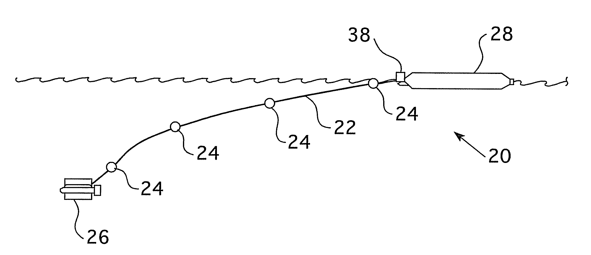
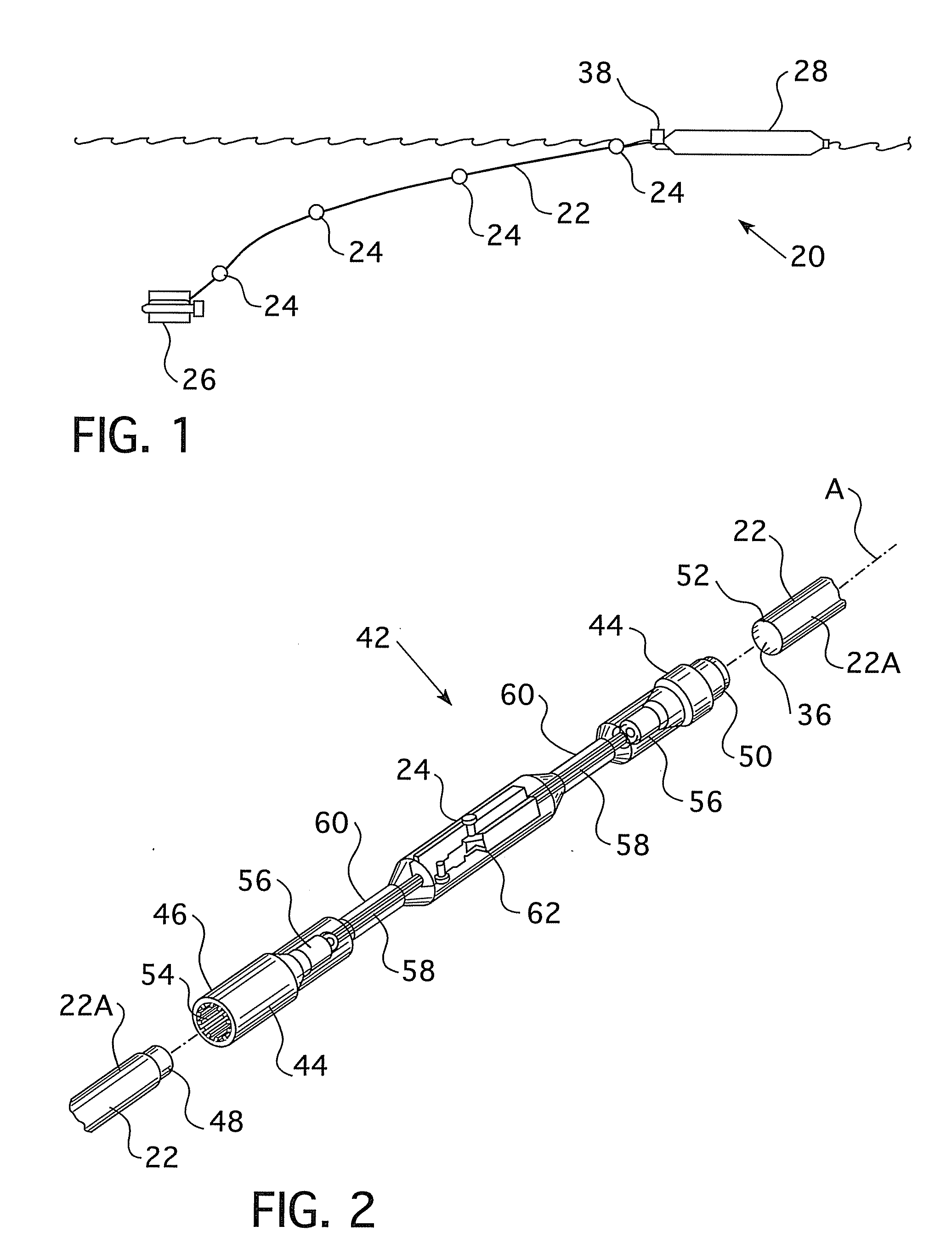
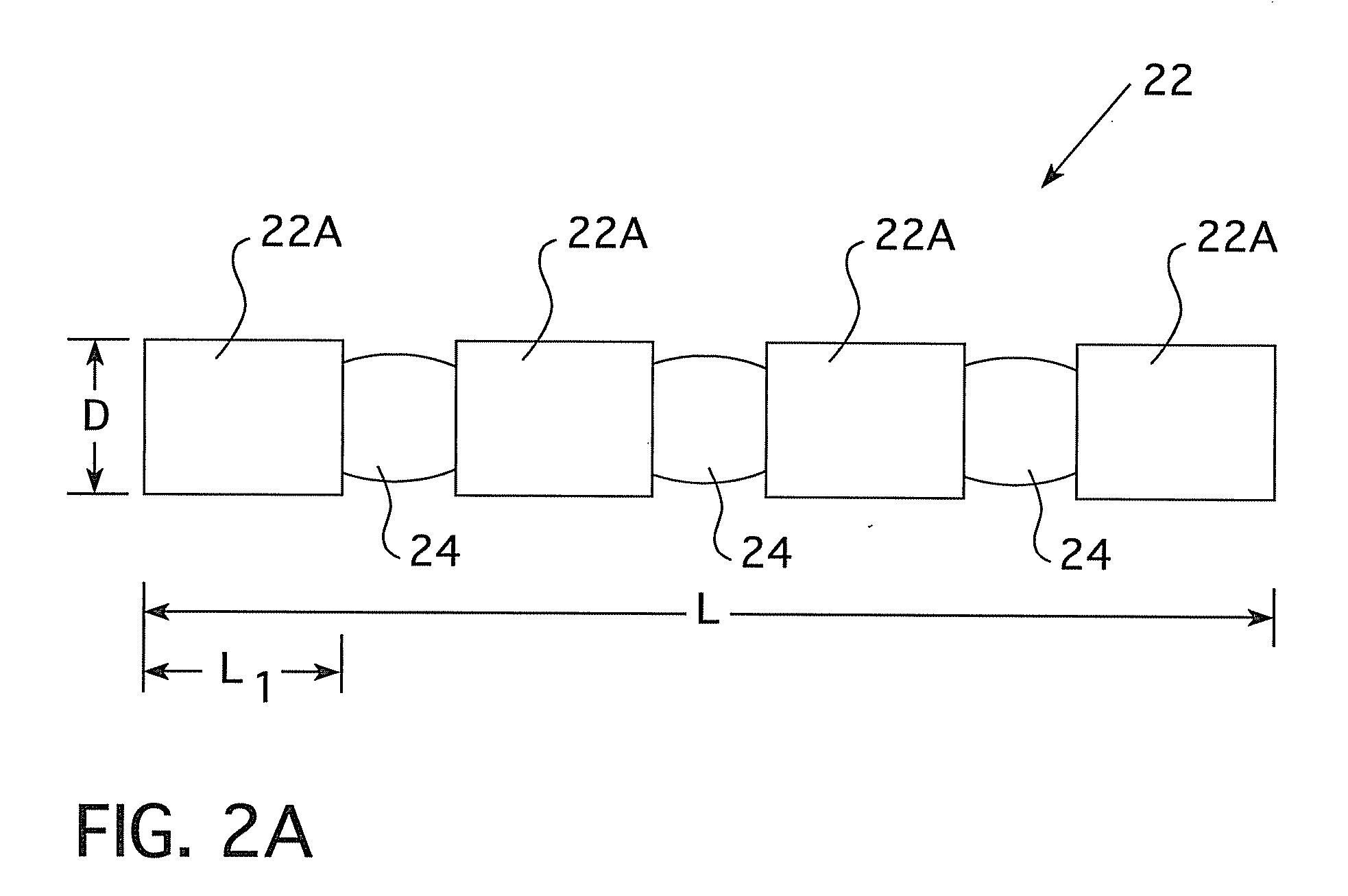
[0039]Referring to FIG. 1, the present invention is directed to a position sensing system 20, including a flexible tether 22 and at least one sensor 24 embedded within a portion of the flexible tether 22. The flexible tether 22 having at least one sensor 24 embedded therein may be disposed between a probe 26 and an analysis platform 28. The system of the present invention has particular utility for...


PUM


Abstract

A position sensing system including a flexible tether and at least one sensor at least partially embedded within a portion of the flexible tether is disclosed. The sensor may be adapted to detect a sensor position factor. The system also includes a communication device adapted to transmit the sensor position factor from the sensor, and a signal processor adapted to receive the sensor position factor. The signal processor is also adapted to calculate at least one of the shape or orientation of the flexible tether from the sensor position factor. The sensor position factor may be relative orientation, relative depth, relative pressure, presence of a magnetic field, presence of an electric field, acceleration, or relative rate of rotation. The system may also include a probe connected to the flexible tether, and the signal processor may calculate the orientation of the probe from the sensor position factor.

Description

CROSS REFERENCE TO RELATED APPLICATION[0001]This patent application claims priority to U.S. Provisional Application Ser. No. 60 / 885,884 filed Jan. 20, 2007, the entire disclosure of which is herein incorporated by reference.STATEMENT REGARDING FEDERALLY SPONSORED RESEARCH[0002]This invention was made with United States government support under U.S. Navy STTR (SBIR) ONR Award No. N00014-05-C-0359. The government has certain rights in this invention.BACKGROUND OF THE INVENTION[0003]1. Field of the Invention[0004]The subject invention relates generally to tether positioning systems and tether shape measuring systems and, more particularly, to tether shape measuring systems used for underwater navigation or localization.[0005]2. Description of Related Art[0006]United States Navy and commercial ships face a variety of distributed and challenging threats to the security of both personnel and assets. One such threat is explosive magnetic limpet mines which are attachable to ship hulls, pro...

Claims


Application Information

Patent Timeline
Patent Type & Authority Applications(United States)
IPC IPC(8): G01B7/00
CPCG01V1/201G01V1/3835
Inventor FRANK, JEREMY E.GEIGER, RICHARDKRAIGE, DAVID R.MURALI, ARUN
Owner KCF TECHNOLOGIES
Learn More