
Signature Apparatus, Verifying Apparatus, Proving Apparatus, Encrypting Apparatus, and Decrypting Apparatus

a verification apparatus and verification method technology, applied in the field of verification apparatus, can solve the problems of ineffective efficiency decryption method and insufficient proof of crypto scheme safety, and achieve the effect of reducing the amount of calculation and high safety

Active Publication Date: 2008-12-04
NEC CORP
View PDF1 Cites 13 Cited by
  • Summary
  • Abstract
  • Description
  • Claims
  • Application Information

AI Technical Summary

Benefits of technology

[0021]The Schnorr signature scheme (Non-Patent Document 10) is one of the signature schemes having such a probability. Although the base problem, that is, a discrete logarithm problem has a safety of about λ bits, the safety proof (Non-Patent Documents 6 and 8) of the Schnorr signature scheme ensures that the Schnorr signature scheme has at most a safety of about λ / 2 bits. Therefore, a signature scheme capable of efficiently reducing the signature text counterfeit problem to the discrete logarithm problem is required.
[0065]According to the present invention, the hash value is used as a commitment, so that it is possible to summarize secret information of an attacker from the commitment without rewinding the attacker and to ensure a higher safety than that of a Schnorr signature scheme. In addition, one-time power residue calculation is performed in each of the signature and verification calculations, thus it is possible to lower an amount of calculation in the signature and verification calculations.DESCRIPTION OF EXEMPLARY EMBODIMENTS

Problems solved by technology

Among the current used crypto schemes, an efficient decryption method has not yet been implemented, and safety of most crypto schemes has not been proven.

Method used


Image

  • Signature Apparatus, Verifying Apparatus, Proving Apparatus, Encrypting Apparatus, and Decrypting Apparatus
  • Signature Apparatus, Verifying Apparatus, Proving Apparatus, Encrypting Apparatus, and Decrypting Apparatus
  • Signature Apparatus, Verifying Apparatus, Proving Apparatus, Encrypting Apparatus, and Decrypting Apparatus

Examples


first exemplary embodiment

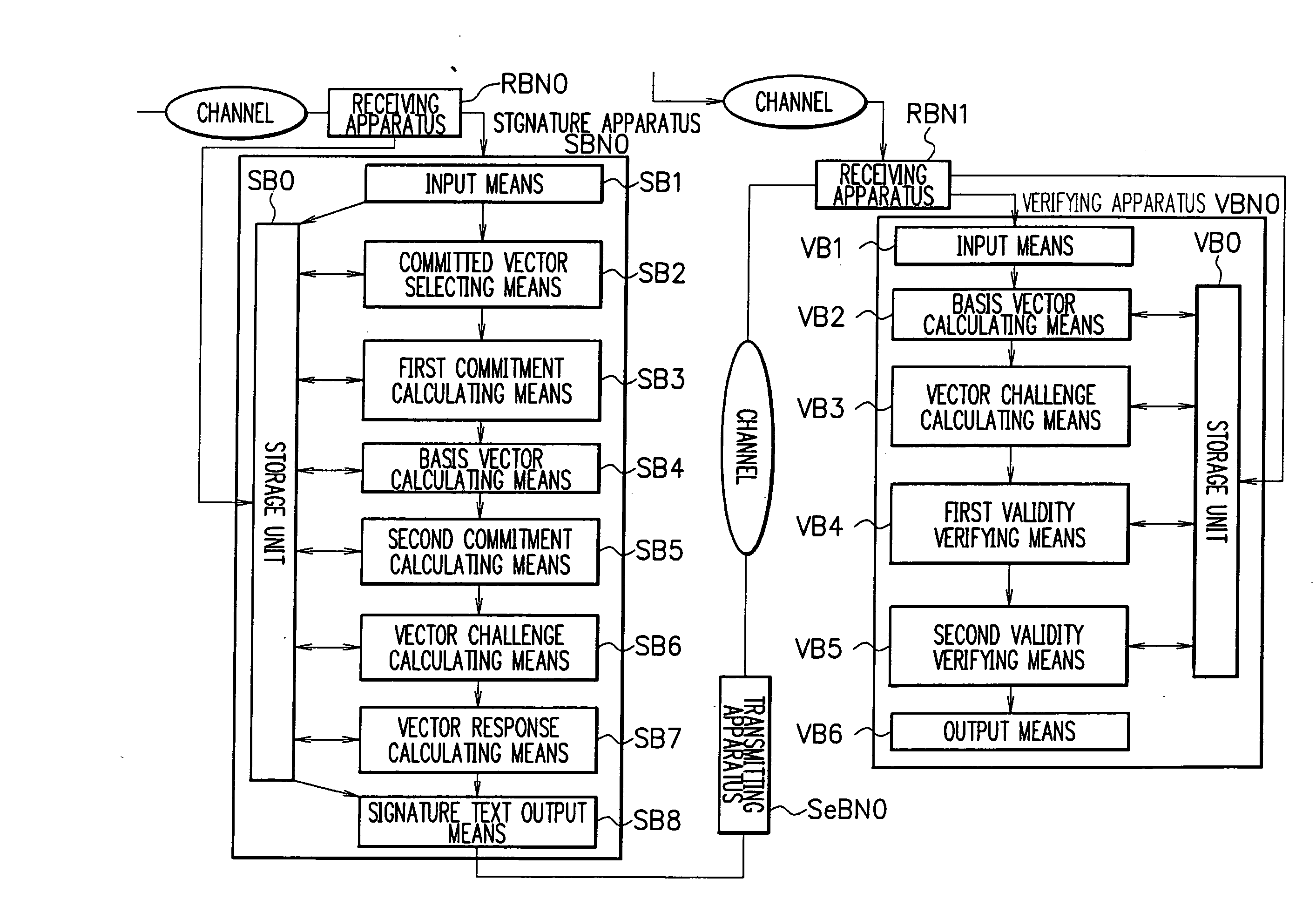
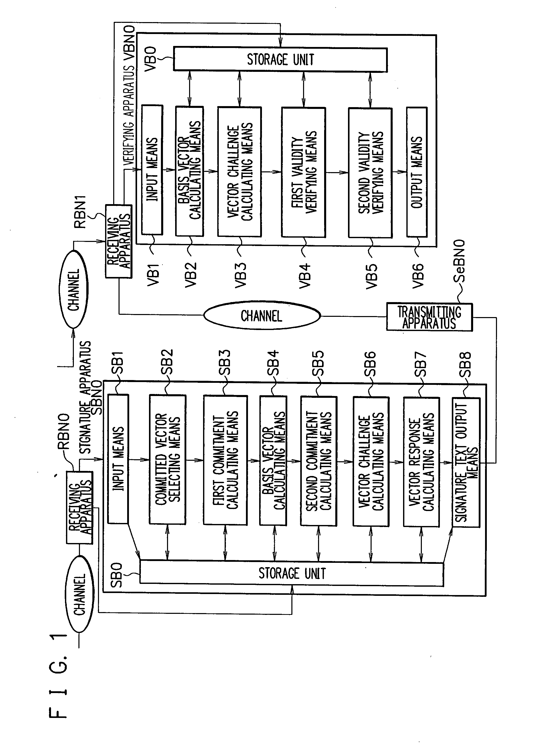
[0067]FIG. 1 is a block diagram illustrating configurations of a signature apparatus SBN0 and a verifying apparatus VBN0 according to a first exemplary embodiment. The signature apparatus SBN0 receives data by using a receiving apparatus RBN0 and transmits data through a transmitting apparatus SeBN0. The verifying apparatus VBN0 receives data by using a receiving apparatus RBN1. For example, LAN or Internet can be used as a channel used for data communication, but the present invention is not limited thereto.

[0068]Now, symbols used in the embodiment are described.

[0069]Symbol A denotes a cyclic group of which order is q. The number of bits of the order q is κ. Symbol g denotes a base point of the cyclic group A. It is assumed that, although the order q of the cyclic group A is publicized, the discrete logarithm problem associated with the cyclic group A is hard to falsify.

[0070]Symbol Z denotes a ring of all integers. Symbol N denotes a set of all natural numbers. An i-th component ...

second exemplary embodiment

[0103]FIG. 1 is a block diagram illustrating configurations of a signature apparatus SBN0 and a verifying apparatus VBN0 according to a second exemplary embodiment. The signature apparatus SBN0 receives data by using a receiving apparatus RBN0 and transmits data through a transmitting apparatus SeBN0. The verifying apparatus VBN0 receives data by using a receiving apparatus RBN1. For example, LAN or Internet can be used for transmission / reception of data, but the present invention is not limited thereto.

[0104]Now, symbols used in the embodiment are described.

[0105]Symbol A denotes a cyclic group of which order is q. The number of bits of the order q is κ. Symbol g denotes a base point of the cyclic group A. In addition, it is assumed that, although the order q of the cyclic group A is publicized, the discrete logarithm problem associated with the cyclic group A is hard to falsify.

[0106]Symbol Z denotes a ring of all integers. Symbol N denotes a set of all natural numbers. An i-th co...

third exemplary embodiment

[0136]FIG. 8 is a block diagram illustrating configurations of a signature apparatus SB30 and a verifying apparatus VBN30 according to a third exemplary embodiment. The signature apparatus SB30 receives data by using a receiving apparatus RBN30 and transmits data through a transmitting apparatus SeBN30. The verifying apparatus VBN30 receives data by using a receiving apparatus RBN31. For example, LAN or Internet can be used for transmission / reception of data, but the present invention is not limited thereto.

[0137]Now, symbols used in the embodiment are described.

[0138]Symbol A denotes a cyclic group of which order is q. The number of bits of the order q is κ. Symbol g denotes a base point of the cyclic group A. It is assumed that, although the order q of the cyclic group A is publicized, the discrete logarithm problem associated with the cyclic group A is hard to falsify.

Symbol Z denotes a ring of all integers. Symbol N denotes a set of all natural numbers. An i-th component of a ve...


PUM


Abstract

Provided are a signature apparatus, a verifying apparatus, a proving apparatus, an encrypting apparatus, and a decrypting apparatus capable of efficiently reducing a signature text counterfeit problem to a discrete logarithm problem. The commitment is a hash value of a set of a value to be committed. Data including a pair of elements of a cyclic group associated with a discrete logarithm problem is used as a public key, and a discrete logarithm of an order of the pair is used as a secret key. Accordingly, it is possible to summarize secret information of an attacker from the commitment without rewinding the attacker and to ensure a higher safety than that of a Schnorr signature scheme. In addition, one-time power residue calculation is performed in each of the signature and verification calculations, so that it is possible to lower an amount of calculation in the signature and verification calculations.

Description

[0001]This application is the National Phase of PCT / JP2005 / 022875, filed Dec. 13, 2005, which claims priority to Japanese Application No. 2005-014891, filed Jan. 12, 2005, the disclosures of which are hereby incorporated by reference in their entirety.TECHNICAL FIELD[0002]The present invention relates to a signature apparatus, a verifying apparatus, a proving apparatus, an encrypting apparatus, and a decrypting apparatus and, more particularly, to a signature apparatus, a verifying apparatus, a proving apparatus, an encrypting apparatus, and a decrypting apparatus capable of efficiently reducing a signature text counterfeit problem to a discrete logarithm problem.BACKGROUND ART[0003]A public key is a cipher which uses different keys for encrypting and decrypting. The key used for the decrypting is maintained in a secret state, while the key used for the encrypting is publicized. The public key needs a system for ensuring an authenticity of a key to be publicized. However, there is n...

Claims


Application Information

Patent Timeline
IPC IPC(8): H04L9/06
CPCH04L9/3013H04L9/3247H04L9/3218G09C1/00
Inventor TERANISHI, ISAMU
Owner NEC CORP
Learn More