Fuel Injection Valve

a fuel injection valve and valve body technology, applied in the direction of liquid fuel feeders, machines/engines, mechanical equipment, etc., can solve the problems of undesired high degree of solidborne sound transmission, clear negative audible, and limited effectiveness of sleeves to transmit hold-down forces to the fuel injection valve. , to achieve the effect of significantly reducing the solidborne sound transmission from the fuel injection valve into the cylinder head

Inactive Publication Date: 2008-12-11
ROBERT BOSCH GMBH
View PDF25 Cites 68 Cited by
  • Summary
  • Abstract
  • Description
  • Claims
  • Application Information

AI Technical Summary

Benefits of technology

[0004]The fuel injection device according to example embodiments of the present invention provides that the solidborne transmission of sound from the fuel injection valve into the cylinder head is significantly reduced. According to example embodiments of the present invention, this is achieved in that the fuel injection valve is connected directly to t

Problems solved by technology

Due to its tube-shaped structure, the sleeve can transmit the hold-down forces to the fuel injection valve with only limited effectiveness.
This design has the result that, by the hold-down force and also by the high fuel pressure present inside the fuel distributor line, t

Method used


Image

  • Fuel Injection Valve
  • Fuel Injection Valve
  • Fuel Injection Valve

Examples


Embodiment Construction

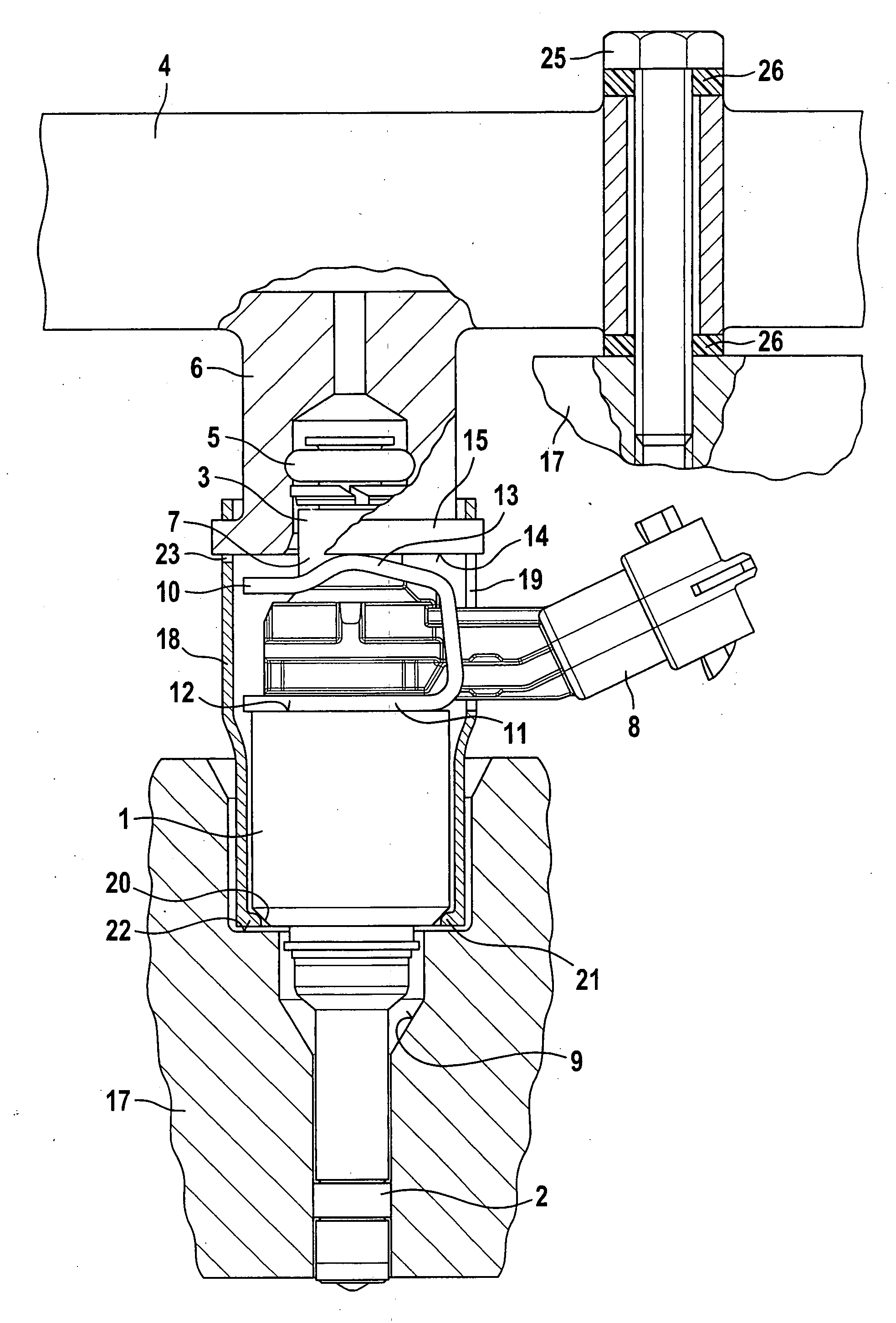
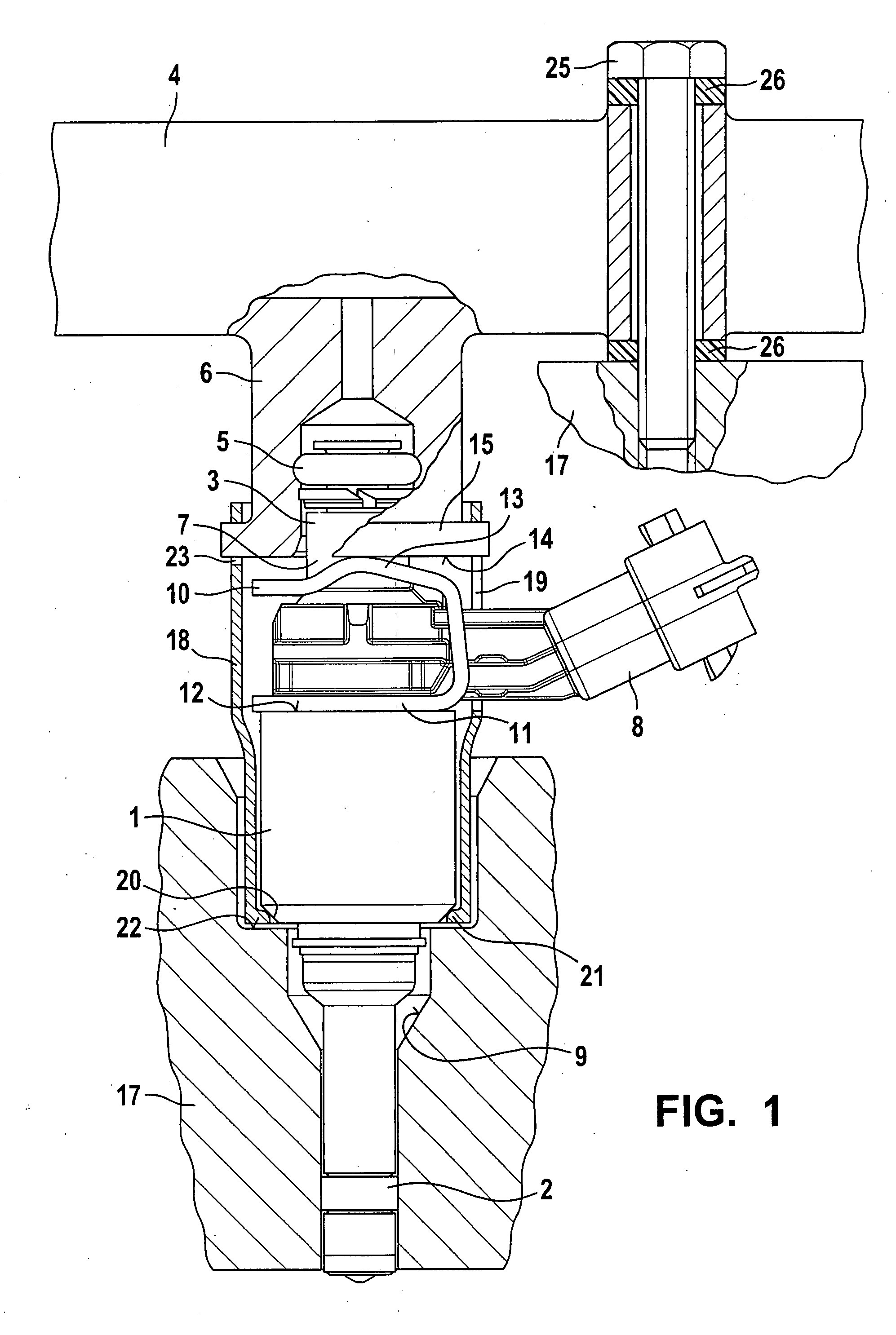
[0029]In FIG. 1, as a first exemplary embodiment a valve is shown in the form of an injection valve 1 for fuel injection systems of mixture-compressing externally ignited internal combustion engines, in a side view. Fuel injection valve 1 is part of a fuel injection device according to an example embodiment of the present invention. With a downstream end, fuel injection valve 1, which is realized in the form of a direct-injecting injection valve for the direct injection of fuel into a combustion chamber of the internal combustion engine, is installed in a receptacle bore 9 of a cylinder head 17 (shown only schematically). A sealing ring 2, made in particular of Teflon®, provides an optimal sealing of fuel injection valve 1 against the wall of receptacle bore 9 of cylinder head 17.

[0030]Fuel injection valve 1 has at its inlet end 3 a plug connection to a fuel distributor line 4, which is sealed by a sealing ring 5 between a fitting 6 of fuel distributor line 4, which is shown in sect...


PUM


Abstract

The fuel injection device provides a particularly effective sound-decoupling construction. The fuel injection device has at least one fuel injection valve, a receptacle bore for the fuel injection valve in a cylinder head, and a fuel distributor line having a fitting in which the fuel injection valve is placed in partially overlapping fashion. A connecting element is situated in the receptacle bore such that the fuel injection valve is held in the connecting element such that the fuel injection valve and the connecting element are held so that they do not contact any surfaces or walls of the receptacle bore of the cylinder head that do not run axially parallel to the fuel injection valve. For this purpose, the connecting element is attached immediately on the fitting of the fuel distributor line.
The fuel injection valve is particularly well-suited for use in fuel injection systems of mixture-compressing externally ignited internal combustion engines.

Description

FIELD OF THE INVENTION[0001]The present invention relates to a fuel injection device.BACKGROUND INFORMATION[0002]German Published Patent Application No. 101 08 193 describes a fastening device for the mutual fastening of a fuel injection valve in a cylinder head of an internal combustion engine, and of the fuel injection valve to a fuel distributor line. The fastening device includes a sleeve that is clamped between a shoulder of the fuel distributor line and a shoulder of the fuel injection valve and is made of an elastic material. Due to its tube-shaped structure, the sleeve can transmit the hold-down forces to the fuel injection valve with only limited effectiveness. The surfaces of the sleeve acting as a hold-down device that are loaded by the shoulders of the fuel injection valve and of the fuel distributor line represent the cutting edges that result from the manner in which the blank for the sleeve is manufactured. The fuel injection valve is placed into a receptacle bore of ...

Claims


Application Information

Patent Timeline
IPC IPC(8): F02M61/14
CPCF02M55/025F02M61/14F02M2200/858F02M2200/803F02M2200/856F02M61/168F02M2200/853
Inventor FUERST, THOMASBOLZ, THILORIEMER, MARTINRETTIG, INGOGUENGOER, GOEKHAN
Owner ROBERT BOSCH GMBH
Why Eureka
Try Eureka