Waveguide phase plug

a phase plug and waveguide technology, applied in the direction of transducer details, instruments, casings/cabinets/drawers of electric apparatus, etc., can solve the problems of dramatically increasing the size of the device, reducing the perceived sound quality, and the absorption wall cannot effectively attenuate the reflected waves. , to achieve the effect of reducing all undesirable sound propagation, increasing the perceived sound quality, and being easy to absorb

Inactive Publication Date: 2010-05-04
GEDDES EARL RUSSELL
View PDF21 Cites 13 Cited by
  • Summary
  • Abstract
  • Description
  • Claims
  • Application Information

AI Technical Summary

Benefits of technology

[0018]The foam plug acts to reduce all undesirable sound propagation to a far greater extent than the desired sound, thus creating a considerable increase in the perceived sound quality of devices which incorporate this technology.

Problems solved by technology

This, however, is problematic and less than completely effective.
First the walls would have to be made of a soft absorptive material which would have to be fairly thick, thus dramatically increasing the size of the device.
Further, absorptive walls would not effectively attenuate the reflected waves that do not intersect the walls.
All in all, this idea is found to be impractical and not totally effective.

Method used


Image

  • Waveguide phase plug
  • Waveguide phase plug
  • Waveguide phase plug

Examples


Embodiment Construction

[0023]It is the purpose of this invention to disclose an improved horn / waveguide for sound radiation.

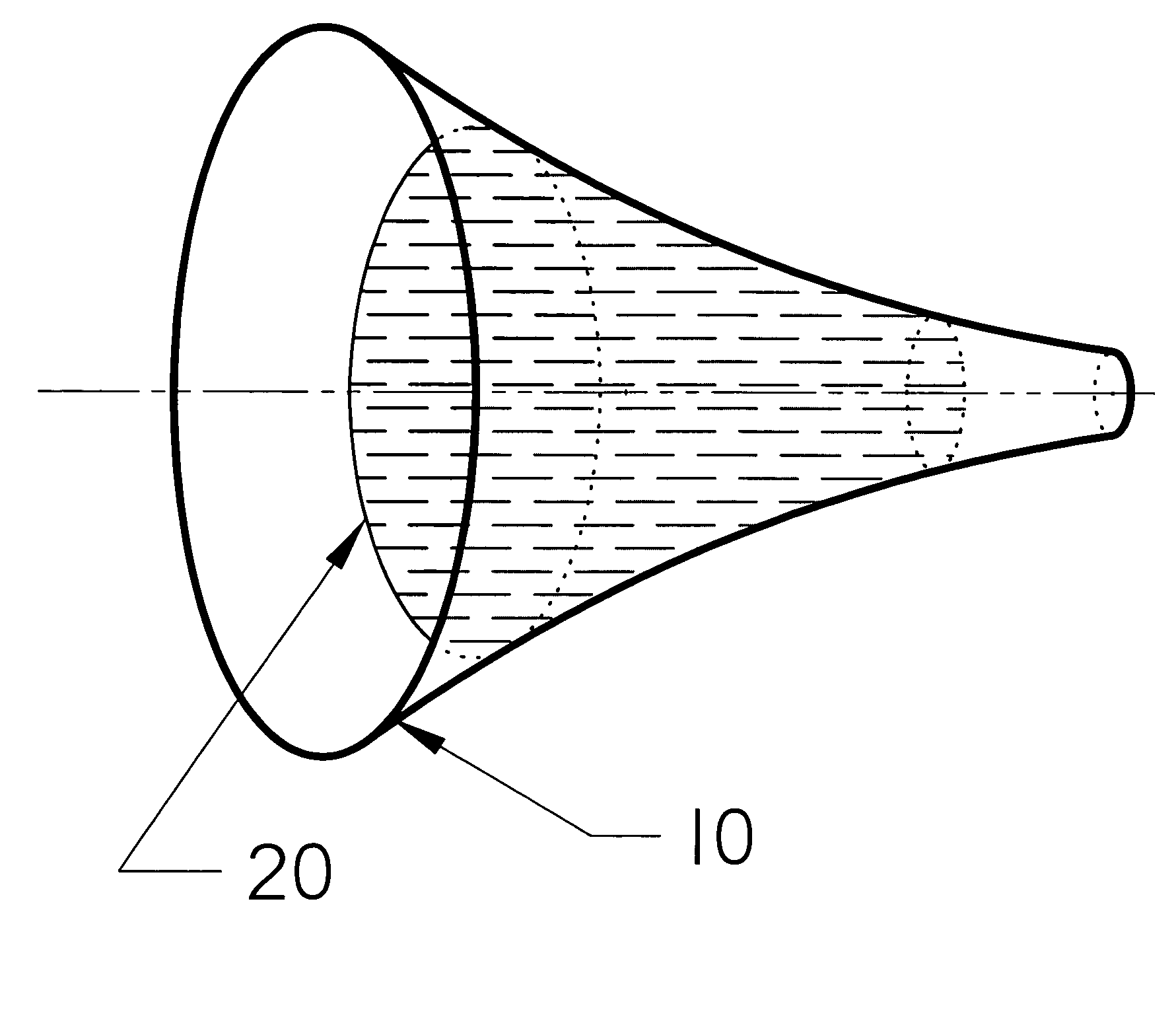
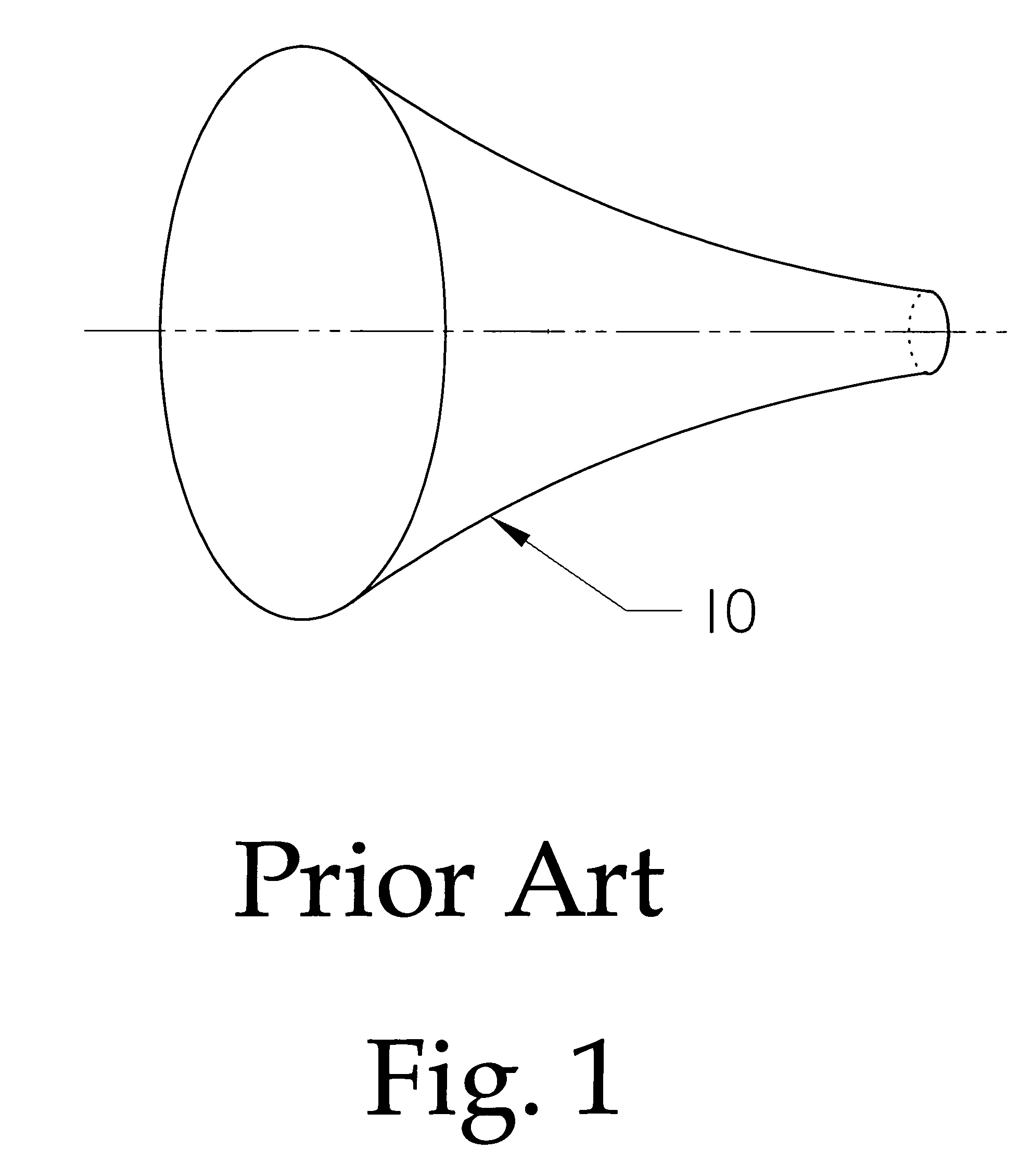
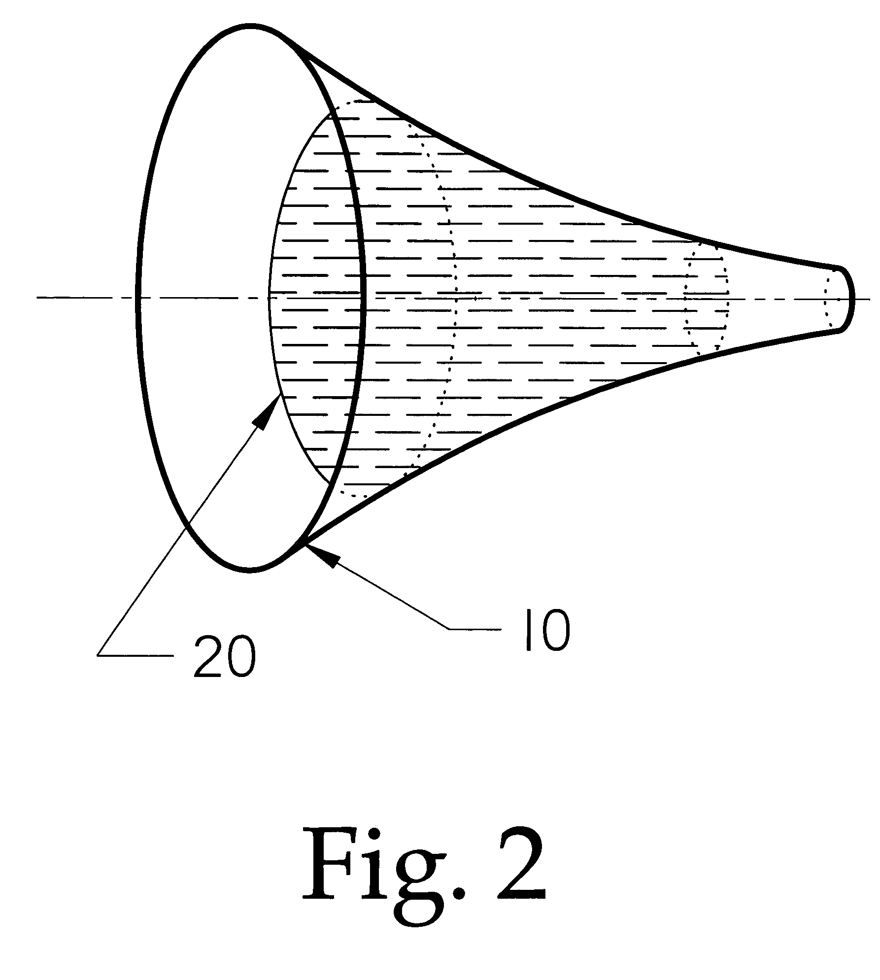
[0024]In the preferred embodiment a piece of open cell polyurethane foam is fabricated so that it fits neatly into the interior of a horn. Shown in FIG. (1), prior art, a horn (10) is filled with air, or said to be unfilled. Shown in FIG. (2) is a preferred embodiment, wherein a portion of the horn (10) is filled with an open cell polyurethane foam (20) such that sound passes through the foam, but is attenuated and delayed by the forced passage through the various channels within the foam.

[0025]It is found in practice that a foam density of between 20 to 30 pores per inch (ppi) had the desired amount of attenuation. The greater the number of ppi, the smaller the holes and the greater the attenuation. Too high a value of ppi results in too much attenuation while too low a value of ppi results in almost no effect at all.

[0026]FIG. (3) shows several implementations of foam plugs (20) sh...


PUM


Abstract

An improved horn for a compression driver which has an interior foam plug for reducing the amplitude of unwanted non-fundamental wave propagation and better control over the sound radiation pattern of the device.

Description

FIELD OF THE INVENTION[0001]The present invention pertains to the improvement in sound quality of a horn or waveguide used for acoustic loading and sound radiation control on an electro-acoustic transducer in an audio loudspeaker system.BACKGROUND OF THE INVENTION[0002]In the area of audio loudspeakers it is common to use compression drivers for mid to upper frequencies. There are two main reasons for this. First, the compression driver, when coupled to a waveguide (in this application the terms waveguide and horn are synonymous), provides for much higher electro-acoustical efficiency than a direct radiating loudspeaker can achieve. Second, the waveguide provides for better control over the directional characteristics of the sound radiation than can be achieved with a direct radiator loudspeaker. In order to effectively control the sound radiation, the waveguide must be capable of manipulating the sound wavefronts.[0003]The traditional way of manipulating the wavefront is with diffr...

Claims


Application Information

Patent Timeline
Patent Type & Authority Patents(United States)
IPC IPC(8): G10K11/04
CPCH04R1/30G10K11/025
Inventor GEDDES, EARL RUSSELL
Owner GEDDES EARL RUSSELL
Why Eureka
Try Eureka