Device for Moving and Treating Volumes of Liquid

a technology for moving and treating volumes, applied in the direction of positive displacement liquid engines, thin material processing, pumps, etc., can solve problems such as the number of contacts

Inactive Publication Date: 2008-12-11
COMMISSARIAT A LENERGIE ATOMIQUE ET AUX ENERGIES ALTERNATIVES
View PDF7 Cites 82 Cited by
  • Summary
  • Abstract
  • Description
  • Claims
  • Application Information

AI Technical Summary

Benefits of technology

[0017]The invention relates to a device for displacing a small volume of liquid under the effect of an electric control, including a first substrate with a hydrophobic surface, provided with first electrically conducting means, with second electrically conducting means positioned facing the first conductin

Problems solved by technology

In certain cases, the problem is posed of performing a displacement and a detection of a characteristic of a volume of liquid, either displaced or to be displaced.
The problem is then often posed of the number of contacts on the chip on which the displacemen

Method used


Image

  • Device for Moving and Treating Volumes of Liquid
  • Device for Moving and Treating Volumes of Liquid
  • Device for Moving and Treating Volumes of Liquid

Examples


Embodiment Construction

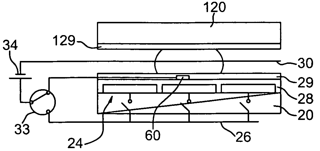
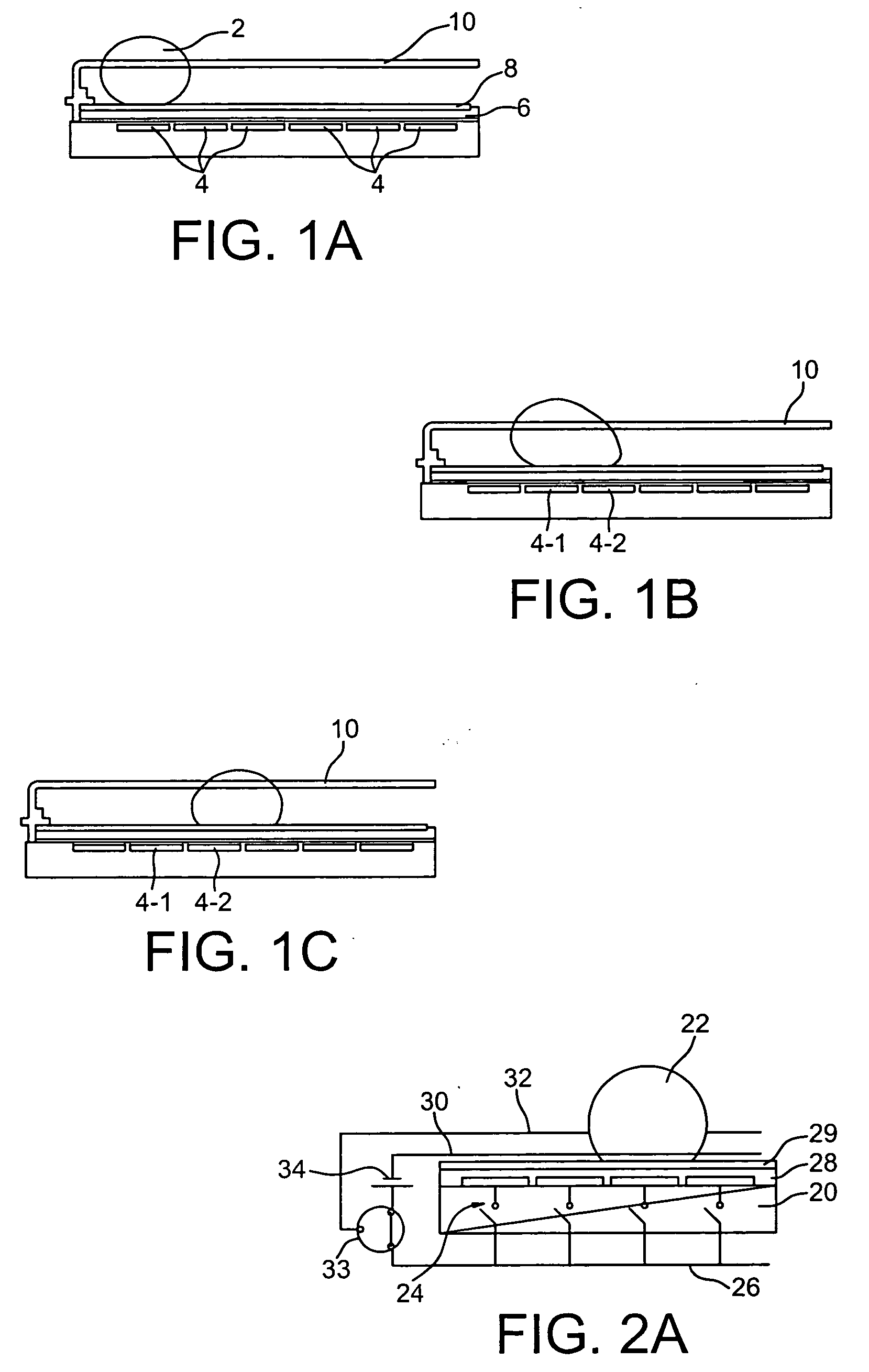
[0057]A first exemplary embodiment of the invention is illustrated in FIGS. 2A and 2B.

[0058]A device or a microfluidic component, according to the invention includes a lower substrate 20, provided with a matrix 24 of independent electrodes.

[0059]Each of these electrodes 24 is electrically connected to a conductor 26.

[0060]The electrodes 24 are covered with an insulating layer 28 and a hydrophobic layer 29.

[0061]The hydrophobicity of this layer means that a drop 22 has a contact angle on this layer, larger than 90°.

[0062]A single layer may combine both of these functions, a Teflon layer for example.

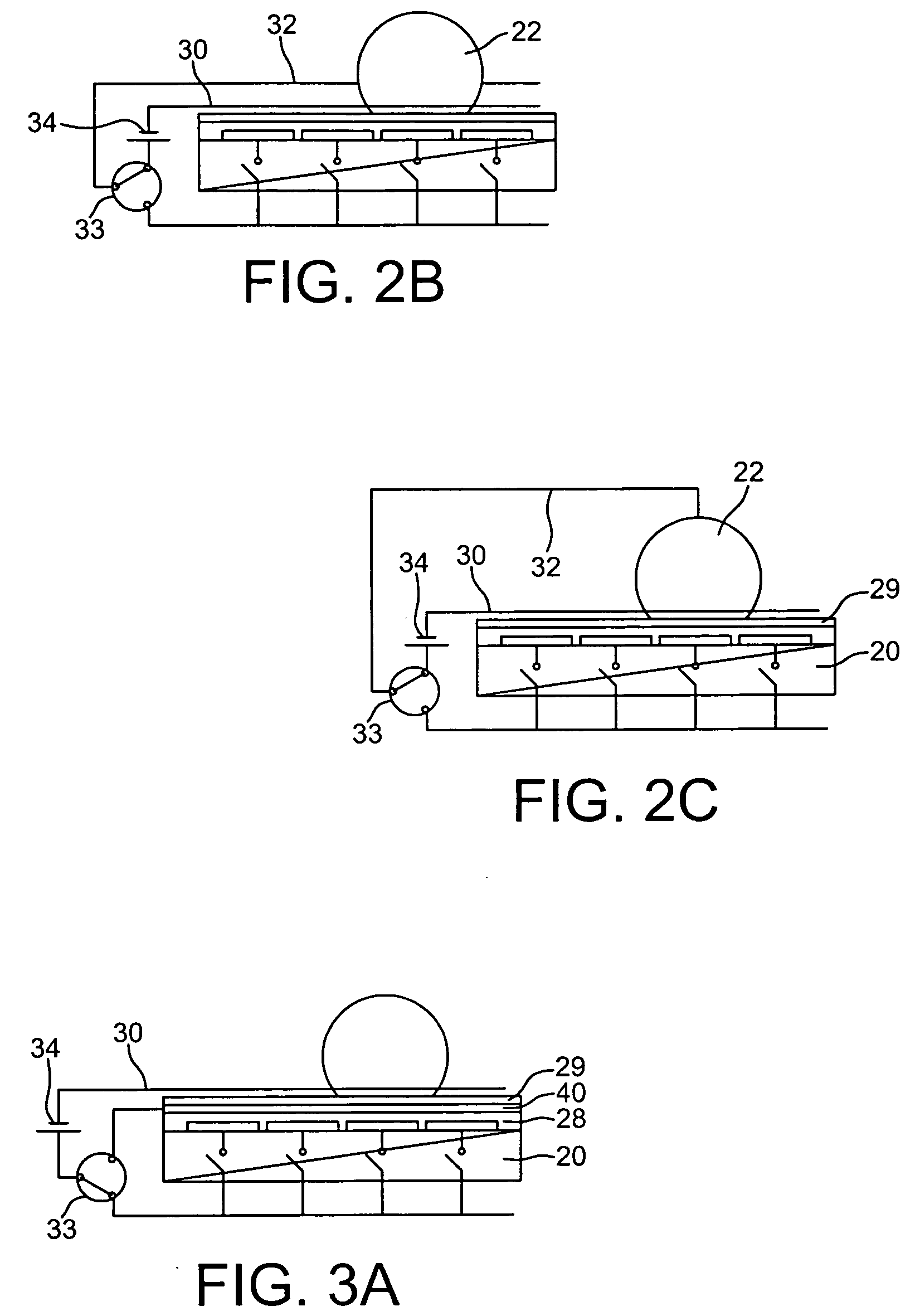
[0063]This device includes a first catenary 30, allowing electrowetting, and a second catenary 32 forming an electrode pair with the first catenary 30.

[0064]The first catenary is located facing the electrodes 24 or the portion of the hydrophobic surface 29 located above the electrodes 24.

[0065]Power supply means 34 connect these different electrodes to each other.

[0066]In FIGS. 2A-2B, thes...


PUM


Abstract

A device for displacing a small volume of liquid under the effect of an electric control, including a first substrate with a hydrophobic surface provided with a first electrical conductor, a second electrical conductor positioned facing the first conductor, and a third conductor, forming with the second conductor, a mechanism for analyzing or heating a volume of liquid.

Description

TECHNICAL FIELD AND PRIOR ART[0001]The invention relates to a device and a method for displacing small volumes of liquid, applying electrostatic forces in order to obtain this displacement.[0002]The invention notably relates to a discrete microfluidic or drop microfluidic handling device, for chemical or biological applications.[0003]One of the most used displacement or handling methods, is based on the principle of electrowetting on a dielectric, as described in the article of M. G. Pollack, A. D. Shendorov, R. B. Fair, entitled <<Electro-wetting-based actuation of droplets for integrated microfluidics>>, Lab Chip 2 (1) (2002) 96-101.[0004]The forces used for the displacement are electrostatic forces.[0005]Document FR 2 841 063 describes a device applying a catenary facing activated electrodes for the displacement.[0006]The principle of this type of displacement is synthesized in FIGS. 1A-1C.[0007]A drop 2 lies on an electrode network 4 from which it is isolated by a di...

Claims


Application Information

Patent Timeline
IPC IPC(8): F15C1/00B01L3/00B01L99/00B01L7/00F04B19/00
CPCB01L3/5025B01L3/502792B01L2300/0645B01L2300/0816B01L2300/1816B01L2300/165B01L2300/1827B01L2400/0427F04B19/006B01L2300/089Y10T137/206Y10T137/2185
Inventor MARCHAND, GILLESFOUILLET, YVESCLEMENTZ, PHILIPPE
Owner COMMISSARIAT A LENERGIE ATOMIQUE ET AUX ENERGIES ALTERNATIVES
Why Eureka
Try Eureka