Curtain body positioning control structure for the window curtain

a control structure and window curtain technology, applied in the direction of door/window protective devices, building components, constructions, etc., can solve the problems of affecting the service life of the curtain, the curtain is not rolled up properly, and the curtain is easily stowed, etc., to achieve convenient operation, reduce the detent force, and reduce the effect of tenseness

Inactive Publication Date: 2008-12-11
WONG MING LU
View PDF3 Cites 12 Cited by
  • Summary
  • Abstract
  • Description
  • Claims
  • Application Information

AI Technical Summary

Benefits of technology

[0003]It is therefore a primary object of present invention to provide a curtain body positioning control structure for the window curtain, which can be easily operated.
[0004]It is a further object of present invention to provide a curtain body positioning control structure for the window curtain to keep the curtain position from sliding.
[0005]The curtain body positioning control structure for the window curtain of the present invention comprises particularly a shaft extruding from a fixing base which is coupling with the bead-chain driving mechanism, locking device and fixing base sequentially; wherein said locking device consisting of top push block and locking block; thereat the combination of locking device with locking block is maintaining an active condition, due to the said locking block is pushed against a spring. In addition, there are retaining grooves for the rolling beads corresponding to the said fixing base, said locking device and said locking block respectively; therein by the time while the rolling beads are connecting to such retaining grooves, if someone would like to open / close such window curtain with the operation of such bead-chain driving mechanism, then a gap between the said locking device and said shaft will be formed with the spring action thereto and hence having an easy operation by reducing lots of detent force thereof. When the curtain stops the operation, said locking device would be swiveled reversely as well as drawn downward by the gravity force of such window curtain, and hence resulting in a certain separation distance of the rolling beads due to the said rolling beads are driven aside from the center of said retaining groove of such rolling beads. Further more, such locking block will be pushed forward caused by the displacement of such rolling beads. While under this circumstance, a cone hole inside the said locking device will be pushed forward to tightly slip onto said shaft, and hence having a positioning effect by preventing such window curtain from falling downward with a locking effect thereof; however, supposed that someone would like to close such curtain furthermore, then it is available for her / him to have the bead-chain to draw the bead-chain driving mechanism downward and also start swiveling thereat, so that the top push block will start swiveling together with the driving block sequentially. Under this way, while the guide incline is being guided with the gap of top push block, it will then being pushed against the drift angle located at the front end of such locking block, and hence creating a displacement of the locking block. Under this circumstance, the central cone hole of said locking block will be released out of cone of shaft of such fixing base from its locking condition, and thus achieving an objective of easy operation as well.

Problems solved by technology

While the curtain is being rolled-up to a certain position, due to the gravity force of such curtain, it will release the driving block of bead-chain swivel base from the spring, so that such spring will be contracted onto such lug, and in this way, such curtain will be locked at certain position with the contraction force of the spring; however, due to the extruding front end of the spring is very tiny and unfixed, the operation of such window curtain could be stuck easily, where it isn't so functional.
More over, when the curtain is being rolled-up, the curtain would always be drawn downward due to the weight of such curtain is higher than the contraction force of spring, and hence resulting in an improper rolled-up position for the curtain, which is being operated uneasily.

Method used


Image

  • Curtain body positioning control structure for the window curtain
  • Curtain body positioning control structure for the window curtain
  • Curtain body positioning control structure for the window curtain

Examples


Embodiment Construction

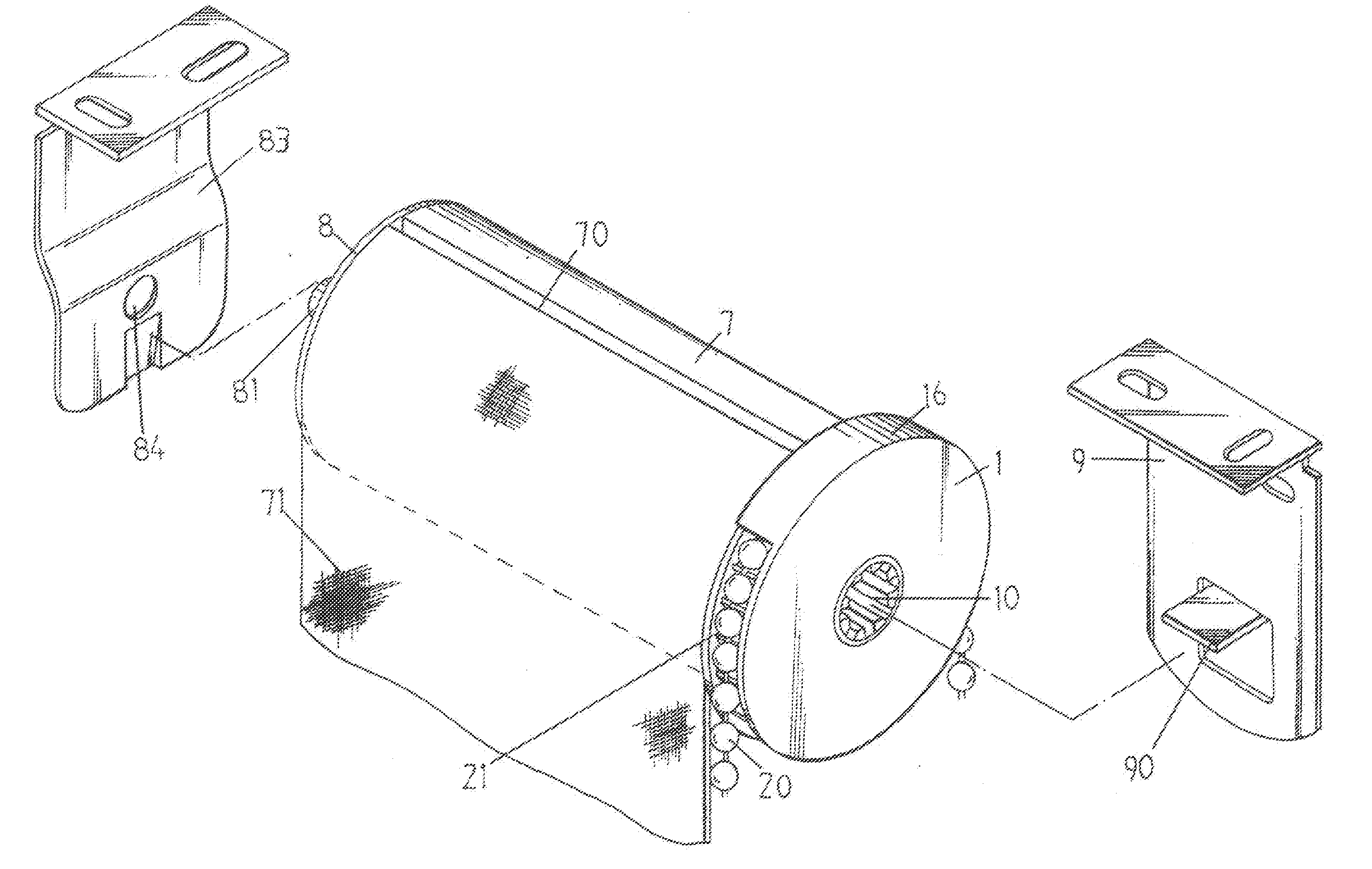
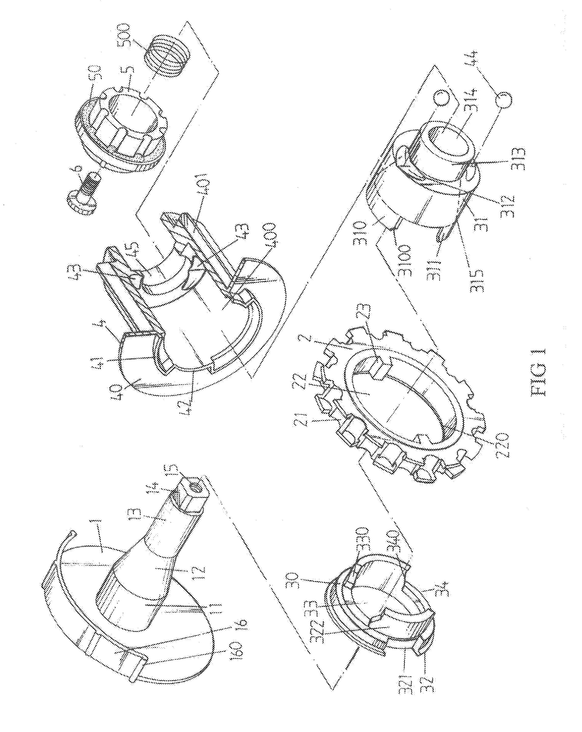
[0018]With reference to both FIG. 1 andFIG. 2, the control structure of the present invention comprises primarily the fixing base 1, the bead-chain driving mechanism 2, the locking device 3 and the fixing base 4, which are all assembled with screws 6 as an integrated structure through the fixing block 5; wherein, the fixing base 1 has a disc block structure, and there are fixing holes 10, locating at the central area of side disc block, equipped for fixing frame. In addition, there is a shaft 11 extruding from the central area of its inner side, wherein the central portion of such shaft 11 is formed as a cone structure 12, and also another the seamy side faces then central is convex to stretch the shaft stem 11. The shaft's stem 11 of medium segment 12 is structured as cone; thereat the front end of such cone 12 has extruded and formed a cylinder with a smaller diameter. Such cylinder 13 has an extruded front end with a square block 14 structure, in which there are screw holes 15 eq...


PUM


Abstract

The present invention relates to a kind of curtain body positioning control structure for the window curtain, there is a shaft extruding from the side fixing base of such window curtain coupling with the bead-chain driving mechanism, locking device and fixing base respectively, wherein the said locking device consisting of top push block and locking block, thereat the combination of locking device with locking block is maintaining an elastic condition, due to such locking block is pushed against a spring, in addition, said fixing base is connected to the said locking device with rolling beads particularly, and in this way while such window curtain is being opened or closed by means of bead-chain driving mechanism, a gap between the said locking device and said shaft will be formed with the spring action thereto and hence reducing lots of detent force accordingly, therefore it has an advantage of easy operation; when the curtain is stopping operation, the locking device would be swiveled reversely as well as drawn downwardly by the gravity force of such window curtain, and hence resulting in a various separation distance of the rolling beads which is caused by the displacement of said rolling beads, and under this circumstance a cone hole inside the said locking device will be pushed forwardly to tightly slip onto the said shaft and hence preventing such window curtain from falling downwardly with a locking effect thereof.

Description

1. FIELD OF THE INVENTION[0001]The present invention relates to a kind of curtain body positioning control structure for the window curtain particularly.2. THE PRIOR ARTS[0002]The current design of control apparatus is for the window curtain with rolling shaft. The concept of its structure technique primarily lies in the lug of side fixing base of such curtain, which has two springs, therein the end of such spring is pushing against the driving block of bead-chain swivel base. When such bead-chain swivel base is revolving, it will push the spring away and hence changing the harnessing condition into the releasing condition. Furthermore it enable the ability to open / close such window curtain. While the curtain is being rolled-up to a certain position, due to the gravity force of such curtain, it will release the driving block of bead-chain swivel base from the spring, so that such spring will be contracted onto such lug, and in this way, such curtain will be locked at certain positio...

Claims


Application Information

Patent Timeline
Patent Type & Authority Applications(United States)
IPC IPC(8): E06B9/36E06B9/324
CPCE06B9/42
Inventor WONG, MING-LU
Owner WONG MING LU
Why Eureka
Try Eureka